• Chinese Optics Letters
  • Vol. 19, Issue 6, 060003 (2021)
Mengyue Xu, Mingbo He, Yuntao Zhu, Lin Liu, Lifeng Chen*, Siyuan Yu**, and Xinlun Cai***
Author Affiliations
  • State Key Laboratory of Optoelectronic Materials and Technologies and School of Electronics and Information Technology, Sun Yat-sen University, Guangzhou 510000, China
  • show less
    DOI: 10.3788/COL202119.060003 Cite this Article Set citation alerts
    Mengyue Xu, Mingbo He, Yuntao Zhu, Lin Liu, Lifeng Chen, Siyuan Yu, Xinlun Cai. Integrated thin film lithium niobate Fabry–Perot modulator [Invited][J]. Chinese Optics Letters, 2021, 19(6): 060003 Copy Citation Text show less
    (a) Schematic of the resonant modulator based on LNOI. (b) Simulated optical TE0 mode profile and electric field distribution. (c) Refractive index change distribution in LN. The applied voltage is 10 V. (d) Scanning electron microscope (SEM) image of the DBR. (e) SEM image of the modulation region.
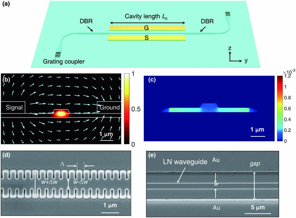
    Fig. 1. (a) Schematic of the resonant modulator based on LNOI. (b) Simulated optical TE0 mode profile and electric field distribution. (c) Refractive index change distribution in LN. The applied voltage is 10 V. (d) Scanning electron microscope (SEM) image of the DBR. (e) SEM image of the modulation region.
    Variation of the LN waveguide effective refractive index (1 V voltage applied) and absorption loss as a function of the electrode gap.
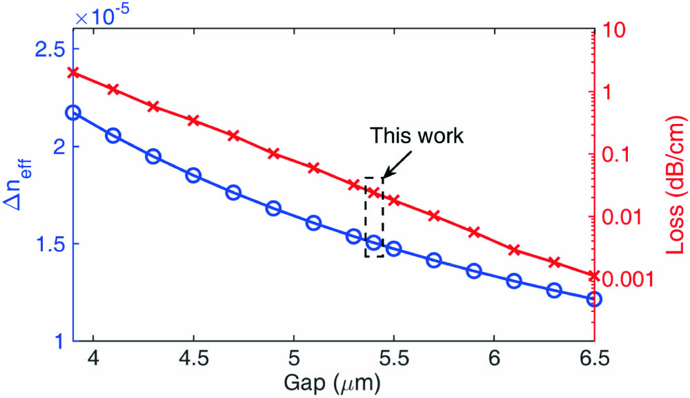
    Fig. 2. Variation of the LN waveguide effective refractive index (1 V voltage applied) and absorption loss as a function of the electrode gap.
    (a) 1 dB bandwidth of stopband versus corrugation depth Δw. (b) Maximum extinction ratio (ER) and quality (Q) factor versus number of grating periods N. (c) Transmission spectra of the FP modulator with different FP cavity length Lc.
    Fig. 3. (a) 1 dB bandwidth of stopband versus corrugation depth Δw. (b) Maximum extinction ratio (ER) and quality (Q) factor versus number of grating periods N. (c) Transmission spectra of the FP modulator with different FP cavity length Lc.
    (a) Measured transmission spectrum of the FP cavity. Inset: the resonance peak at the Bragg wavelength. (b) Measurement and linear fitting of the resonant wavelength shift as a function of the applied DC voltage. Inset: the spectral shift as the voltage sweeps from 0 V to 25 V at different wavelengths.
    Fig. 4. (a) Measured transmission spectrum of the FP cavity. Inset: the resonance peak at the Bragg wavelength. (b) Measurement and linear fitting of the resonant wavelength shift as a function of the applied DC voltage. Inset: the spectral shift as the voltage sweeps from 0 V to 25 V at different wavelengths.
    Measured EO S21 responses at different operation wavelengths. Δλ represents the wavelength offset from the resonance wavelength.
    Fig. 5. Measured EO S21 responses at different operation wavelengths. Δλ represents the wavelength offset from the resonance wavelength.
    (a) Experimental setup for measuring the eye diagram. PC, polarization controller; DUT, device under test; EDFA, erbium-doped fiber amplifier; PRBS, pseudo-random binary sequences. (b) Open eye diagrams with data rates of 20, 40, and 56 Gbit/s.
    Fig. 6. (a) Experimental setup for measuring the eye diagram. PC, polarization controller; DUT, device under test; EDFA, erbium-doped fiber amplifier; PRBS, pseudo-random binary sequences. (b) Open eye diagrams with data rates of 20, 40, and 56 Gbit/s.
    Mengyue Xu, Mingbo He, Yuntao Zhu, Lin Liu, Lifeng Chen, Siyuan Yu, Xinlun Cai. Integrated thin film lithium niobate Fabry–Perot modulator [Invited][J]. Chinese Optics Letters, 2021, 19(6): 060003
    Download Citation