Abstract
We propose a linear mapping relationship between the polarization of the fundamental mode and the cylindrical vector (CV) modes on the first-order Poincaré sphere (FOPS) in fiber. The new method is based on the four-dimensional complex Jones matrices in terms of the linearly polarized mode bases. With our theoretical model, an all-fiber approach to generate arbitrary CV beams on the FOPS is proposed theoretically and verified experimentally. In the experiment, through the combination of a mode converter and a two-segment cascaded few-mode fiber with fixed stresses, it is possible to generate all CV modes on the FOPS by only adjusting the polarization of the fundamental mode. The Stokes parameters of the output light are measured to verify our scheme, which shows good agreement with the theoretical prediction. The method may provide a convenient way to generate CV beams and evolve the polarization states in any path on the FOPS, which is expected to have potential applications in encoding information and quantum computation.1. INTRODUCTION
Polarization, originated from the vectorial nature of electromagnetic field, is exploited in many photonic applications. In the past, the homogeneous polarization representation by Poincaré sphere (PS), such as linear, elliptical, and circular polarizations [1], has drawn great attention. Recently, a light beam with a spatially inhomogeneous state of polarization (SOP), which is referred to as a vector beam, has been investigated because of its unique properties [2,3]. Unlike the conventional homogeneous SOPs, the SOP of a vector beam depends on its transverse profile. Among vector beams, cylindrical vector (CV) beams have received much attention due to their cylindrical symmetry in both polarization and phase, which can be represented by a higher-order Poincaré sphere (HOPS) [4]. The modes on the poles and the equator have especially attracted considerable attention in multiple applications, including optical tweezers [5,6], quantum information processing [7], nanoscale microscopy [8–11], and large-capacity optical communication [12]. The modes along the longitude, which carry tunable average orbital angular momentum (OAM), introduce an extra dimension to control optical systems and thus spur novel applications from atomic manipulation [13,14] to quantum information processing [15].
Driven by their various applications, the generation of CV beams has also emerged as a hot topic. In the free-space system, the optical elements with spatially varying phase distribution, including spatial light modulators (SLMs), q-plates, and metasurfaces, are proposed to generate the modes on the first-order PS (FOPS). Benefitting from its programmability and polarization property, an SLM can be used to generate the desired light field, either in combination with quarter-waveplates (QWPs) or by interfering two SLM-generated coaxial Laguerre Gaussian modes [16–20]. Besides, the modes on FOPS can also be generated by controlling the input polarization of the q-plate and metasurface, which can convert the orthogonal circular polarizations to OAM modes owning opposite topological charges with orthogonal circular polarizations [21–26]. However, the spatial devices are bulky and expensive. Therefore, all-fiber generation is preferred, especially in the scenario of medical endoscopy and optical tweezers. Currently, the generation of CV modes based on few-mode fiber or specially designed fiber attracts increasing interest because these systems possess features of excellent flexibility, robust mode confinement, and compact structure. The all-fiber system CV mode generators consist of two stages: a polarization controller (PC) on the single-mode fiber (single-mode PC) as well as a first-order mode converter before, and a polarization controller on, the few-mode fiber (FMF) [27–40]. The mode-selective converter [27–33], the photonic lantern [34], the fiber grating [35,36], and the lateral offset splicing spot [37–40] act as the first-order mode converter to convert an mode to a first-order mode. The single-mode PC and the PC added on the FMF are adjusted simultaneously to control the polarization state of the output CV mode. The preceding methods do not show very satisfying performance, mostly in three aspects. First, they all only generate four specific CV modes in experiments. Second, how CV modes change, by varying the state of stress on the FMF and the polarization of the fundamental mode, is not explicitly given in the above papers; lacking an explicit function of the CV mode with regard to the stress and polarization, the adjustment of both PCs can hardly follow a clear routine and regulated model. Third, the stress on the FMF has only been adjusted by mechanical or thermal methods so far, which are very inconvenient and slow. Apart from the methods in Refs. [27–40], the CV mode can be generated by adjusting the input polarization state before the fiber grating [41,42]. However, this kind of setup only obtains two modes on the poles [41] or four specific modes on the equator of the FOPS [42].
In this paper, we propose an explicit linear mapping relationship between the polarization of the fundamental mode and the CV modes on the FOPS in an all-fiber system, assisted by the Jones matrix representation. We systematically explain the transmission process of modes in the FMF with stress, in terms of linearly polarized (LP) mode bases. Then, based on the relationship between OAM and LP mode bases, we reveal that, by cascading a photonic lantern and two segments of FMFs with different stresses, the input fundamental mode with a homogeneous polarization state located on the PS can be converted to vector modes on the FOPS at the output. During the process of mode switching, the stress states of the two-segment FMFs are fixed, which can induce the phase differences between the eigenmodes in the first FMF segment and in the second FMF segment. To the best knowledge of the authors, this is the first investigation of all-fiber generation of arbitrary cylindrical vector beams on the first-order PS by only adjusting the polarization of the fundamental mode. The generated vector modes can be changed by adjusting the polarization state of the input fundamental mode, which implies that this system could enable a nanosecond time scale switch with an electronic PC [43]. This would be immensely useful for networking functionalities in mode-division multiplexing schemes, as well as switching bases in higher-dimensional quantum links. The proposed scheme is numerically and experimentally studied. Subsequently, the experimentally measured SOPs of the produced vector modes agree well with the simulated ones.
Sign up for Photonics Research TOC. Get the latest issue of Photonics Research delivered right to you!Sign up now
2. THEORY
A. Higher-Order Poincaré Sphere
The homogeneous polarization state of a mode can be described as a point on the surface of a PS as shown in Fig. 1(a). Algebraically, any point on the polarization PS can be seen as the superposition of two orthogonal circular polarizations, corresponding to the two poles on the polarization PS as shown in Eq. (1): where and are the right and left circular polarizations, and and are two orthogonal linear polarizations along the horizontal and vertical directions. The azimuthal angle and polar angle affect the orientation and ellipticity of the polarization. The points on the PS can be expressed by the following Jones vector, where and are the complex amplitudes of the and modes, respectively:
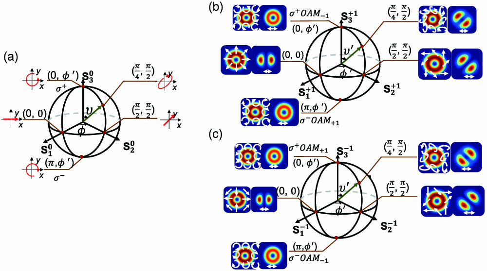
Figure 1.(a) Polarization PS for representing the plane wave states of polarization. (b) The st-order PS and (c) the st-order PS. Modes and polarizations are provided for the states at the poles and for the special points on the equator.
A given polarization can be represented not only by the superposition of two poles but also by the superposition of two points on both sides of the diameter. Thus, the given polarization can also be denoted by the horizontal and vertical polarization bases:
If two points on the arbitrary diameter of the equator are used as the bases of the Jones matrix, the given polarization can be expressed as where and are two orthogonal linear polarizations with angles and to the horizontal directions, respectively. Similarly, the vector beams on the HOPS can be denoted as the linear superposition of two orthogonal circular polarizations with opposite topological charges, corresponding to the two poles on the HOPS. Thus, the points on the HOPS can be denoted by the following equation in terms of the azimuthal and polar angles () in the sphere: where and are the th order OAM modes with right and left circular polarizations. can take an arbitrary integer number ranging from to . The points on the HOPS can also be expressed by a Jones vector, where and are the complex amplitudes of the and modes, respectively:
Equations (3) and (4) indicate that cos () and are the amplitude factors of the two poles, while is the phase difference between the two poles. Figures 1(b) and 1(c) show the mode profiles and polarization states when and (st- and st-order PSs). It can be seen that parameter makes the polarization of each point on the cross section rotate counterclockwise, while parameter affects the polarization ellipticity. Because any point on the HOPS can be regarded as the superposition of two poles with different and , e.g., the amplitudes of the two poles and the phase difference between them, all the vector beams on the HOPS can be achieved by modifying and .
Since the first-order mode group is fourfold degenerated, it is necessary to use four degenerated mode bases (e.g., , , , and ) to denote any first-order mode. For the st-order PS shown in Fig. 1(b), the amplitudes of the and modes are zero. Therefore, the vector modes on the st-order PS can completely characterize a general CV beam. For the st-order PS shown in Fig. 1(c), the amplitudes of the and modes are zero. Thus, the vector modes on the st-order PS can describe the so-called -vector beams [44].
B. Transmission Process of the Modes in the FMF with Stress
In an ideal circular-core FMF, the , , , and modes are the eigensolutions of Maxwell’s equations as shown in Fig. 2(a). is the azimuthal order, while is the radial order of the eigenmodes. We specify the situation of the radial order . In general, the eigenmodes with similar effective refractive index (neff) have similar group velocities and comprise a single mode group. The zeroth-order mode group, also named the fundamental mode, is combined by two degenerated modes ( and ), accounting for the two orthogonal polarization orientations. th () order mode groups consist of four degenerated modes, e.g., the modes for , and for . However, in practice, a disturbance acting on the fiber forces the original isotropic fiber into an anisotropic medium with fast (F) and slow (S) axes. The slow and fast axes are along the stress direction and the orthogonal direction, respectively. The zeroth-order eigenmodes profile keeps the Gaussian distribution, while the higher-order eigenmodes evolve to modes (, and ). Here “” and “” indicate the mode lobe orientations of two orthogonal eigenmodes. The “” orientation aligns with the slow axis of the fiber under stress, while the “” orientation makes an angle with the “” orientation. Also, “” and “” indicate two orthogonal polarization directions with a 90° angle to each other, which are respectively along the slow and fast axes.

Figure 2.(a) Eigenmodes in the FMF without stress. (b) Eigenmodes in the FMF with stress.
As an example, Fig. 2(b) shows the mode profiles of two-mode optical fiber calculated by the finite element method. Attributed to the different effective refractive indexes introduced by the stress, propagation constants of the four eigenmodes are different. Consequently, there will be phase differences between the eigenmodes after transmission. The phase differences can be calculated by , where is the operating wavelength, is the effective refractive index difference accordingly, and L is the stress-applied length. The phase differences between the modes and , and , and and are defined as , and , respectively. When an FMF is under segmented stresses in different magnitudes and directions, the piecewise model can be represented by the Jones matrix as in Eq. (7). For convenience of calculation, the output mode and input mode of the FMF are expressed by the same mode bases (, , , and ), whose mode orientation “” and polarization direction “” are in the same but arbitrary direction. , and are the amplitudes of the , and modes, denoted as where and are the rotation matrix and reverse rotation matrix [45]. represents the angle between the mode orientation of the eigenmode [] of the th-segment FMF and the mode orientation of the input mode basis (). Thus, the matrix is used to convert input mode bases along an arbitrary direction to the mode bases along the direction of eigenmodes for the th-segment FMF, while represents the phase difference matrix in the th-segment FMF.
The higher-order mode can be expressed by either LP mode bases or OAM mode bases [46]. In order to keep the mode bases consistent with the poles on the HOPS, the LP mode bases of the output mode need to be converted to the OAM mode bases. In the FMF, the relationship between the LP mode and the OAM mode is . By combining and , the conversion matrix of the Jones vector between the LP mode bases and OAM mode bases is written as Eq. (10). and , which are the phase terms related to the direction of polarization and mode lobe orientation of , are omitted without affecting the final result: where , , , and are the complex amplitudes of the , , , and modes, respectively.
C. Generation Principle of the CV Modes on the FOPS
Based on the analysis in Section 2.B, we propose a method to achieve a tunable mode on the st-order PS with the given and , by changing the input polarization state. According to Eqs. (7)–(10), and can be calculated by scanning the parameters from to with given input and desired output Jones matrices.
The schematic diagram for generating the st-order PS is plotted in Fig. 3(a). A mode converter (MC) and two-segment FMFs with stresses along different directions are used to generate all the modes on the st-order PS. The MC is used to convert a fundamental mode with the arbitrary SOP on the polarization PS to the mode with the same SOP, which also can be expressed by the same polarization PS. According to Eqs. (2)–(4), the input polarization at the single-mode fiber (SMF) port can be written as Eq. (11) in terms of right and left circular polarizations:
Figure 3.(a) Schematic diagram to generate CV beams. (b) The polarizations and (c) modes along a longitude and a latitude on the two PSs. (b) and (c) show the mapping relationship between two PSs when the angle between polarization and horizontal direction equals 0 deg.
As the MC converts the twofold degenerate fundamental mode to a fourfold degenerate 1st-order mode, the Jones vector shown in Eq. (11) will be extended to a Jones vector. Thus, the output mode of the MC can be expressed as Eq. (12) in terms of the , , , and modes. The mode orientation of and the direction of polarization are the same, which are along the direction of the mode generated by MC as
Then the produced EMC mode is injected into the two-segment FMFs with stresses along different directions. With the angles and in the first and second segment of the FMFs as and , and the phase differences , , in the first and second segment as , , and and , , and , the output mode of the two-segment FMFs can be expressed as Eq. (13) in terms of the , , , and modes:
As the mode bases of are the , , , and modes, in order to be consistent with the mode bases of FOPS, the mode needs to be converted to the mode based on the , , , and modes. According to Eq. (10), the output mode of the two-segment FMFs can be expressed as Eq. (14) in terms of the , , , and mode bases:
According to Eq. (14), the output mode of the two-segment FMFs can be also expressed as Eq. (15). Comparing Eq. (15) and Eq. (5), we find that the relation between and on the HOPS and and on the fundamental PS can be written as and : With appropriate and , the arbitrary cylindrical vector beams represented by the corresponding points (, ) on the st-order PS can be obtained. Figures 3(b) and 3(c) show the situation when the angle between the polarization and the horizontal direction equals 0. If the input SOPs are located on the blue or red trajectory of fundamental PS, the output mode will be located on the same color trajectory of the st-order PS.
3. EXPERIMENTAL SETUP, RESULTS, AND DISCUSSIONS
The experimental apparatus is shown in Fig. 4. The output light of a laser is divided into two paths by a 1:1 optical coupler. The lower branch is used to generate first-order mode beams. The single-mode PC1 is inserted before a mode-selective photonic lantern (MSPL) to produce an arbitrary polarization beam. The to conversion is realized by the MSPL [47], and the converted mode is launched into a step-index FMF. The homemade MSPL is fabricated by together inserting two SMF-28 fibers and a two-mode fiber (OFS) to a capillary with 1.44 refractive index. The final fabricated device has 60 mm transition length, 25.8 μm core diameter, and 105 μm cladding diameter. The numerical aperture of the few-mode end is 0.11. Figure 4(b) shows the microscope image of the few-mode-end cross section of the fabricated MSPL. The near-field mode images at the few-mode end of the MSPL and output of 2 m FMF-tailed from the MSPL at 1550 nm are presented in Fig. 4(c). The FMF pigtail, which is with a core diameter of 16 μm and a 0.55% relative refractive index difference between the core and cladding, is then mounted as coils in two paddle-type PCs. In order to obtain the desired phase differences between egienmodes of the FMF, the effective refractive indices () of the eigenmodes are simulated with COMSOL software for the bent TMF with different radii. The phase differences between the four eigenmodes calculated by are shown in Fig. 4(d). According to the simulation, when the bending radius is 15.5 mm, the two loops can generate , , and phase differences (, ) as shown in the black dots of Fig. 4(d). When the bending radius is 27 mm, the five loops can generate , , and phase differences (, ) as shown in the brown dots of Fig. 4(d). Thus, the FMF is entwined by few-mode PC1 with one, two, and one loop, whose paddle sizes are 31 mm. The one loop of the first and third paddles is for compensating for the unavoidable perturbations of the superfluous FMF, and the two loops are used to generate the desired phase differences. Then, the FMF is entwined by few-mode PC2 with zero, five, and two loops, whose paddle sizes are 54 mm. The five loops are used to generate the desired phase differences, while the two loops are for compensating for the unavoidable perturbations of the superfluous FMF at the output. The direction of the paddle is to the slow axis of the FMF, which is under stress. The desired 45 and 90 deg for the first- and second-segment FMFs are achieved by rotating the paddle’s directions of the few-mode PC1 and PC2. Then, we fix the states of two few-mode PCs and change the input polarization by adjusting a single-mode PC1 to obtain the CV modes on the st-order PS. The upper branch is used as the reference Gaussian beam to record the phase structures of the generated beams. A tunable attenuator is inserted in the reference branch to equalize the power of generated and reference beams to the same order of magnitude. The single-mode PC2 is for obtaining clear interferences. The output beams and their phase structures are recorded by an infrared camera (MicronViewer 7290A) after the generated beam and the reference Gaussian beam travel through object lenses and a nonpolarization beam splitter (NPBS).
Figure 4.(a) Experimental setup to generate CV beams. Single-mode PC, single-mode polarization controller; PL, photonic lantern; Few-mode PC, few-mode polarization controller; Obj., objective; BS, beam splitter; QWP, quarter-wave plate; Pol., polarizer. (b) The microscope image of the few-mode-end cross section of the fabricated MSPL. (c) Near-field mode images at the few-mode end of the MSPL and output of 2 m FMF-tailed from the MSPL. (d) Phase differences between the four egienmodes varying the bending radius.
It is experimentally found that this all-fiber design is capable of producing switchable cylindrical vector beams, and the stable output could operate over one week in the laboratory environment. The insertion loss is 3.18 dB, which is mainly introduced by the homemade photonic lantern. To examine the polarization of the generated vector beams, the Stokes parameters of each point on the cross section are measured by passing through a QP. In the setup, QP consists of a QWP and a polarizer. The Stokes parameters can be denoted by the following equations: where stands for the intensity of the light recorded by the CCD, and and are the optical axis directions of the QWP and the polarizer with respect to the axis, respectively [24]. The Stokes parameter is the intensity distribution of the output beam, which can be recorded by the CCD without QP.
By simply adjusting the single-mode PC1 at the input port, the input SOPs will change continuously following the red and blue trajectories on the polarization PS as shown in Fig. 3(b). First, the single-mode PC1 is adjusted to generate eight polarization states located at red line with , and varies from 0 to at intervals of . The output beams are recorded by projecting their polarizations into the , and sequence of basis and measuring the corresponding intensity at each pixel of CCD camera. The experimentally recorded and numerically calculated intensity profiles on the equator are shown in Figs. 5(a) and 5(b), respectively. Then the single-mode PC1 is adjusted to generate eight polarization states that are located at the blue line with , and varies from to at intervals of . The output beams are also recorded by projecting their polarizations into the , and sequence of basis. The experimentally recorded and numerically calculated intensity profiles on the equator are shown in Figs. 5(c) and 5(d), respectively. In order to determine the helical phase front of poles, the beams passing through the QP interfere with a Gaussian beam.
Figure 5.(a) Experimental results and (b) simulation results when the input polarization is adjusted along the red line on the polarization PS, e.g., , and varies from 0 to at intervals of . (c) Experimental results and (d) simulation results when the input polarization is adjusted along blue line with and varying from to at intervals of .
We calculate the correlation coefficients [48] between the experimental , and modes and the simulated ones as shown in Figs. 6(a) and 6(b). For all the modes, the correlation coefficients are more than 79%. In comparison with the theoretical distributions, the experimental results verify that the emerging beams are the desirable CV beams on the st-order PS.
Figure 6.Correlation coefficients for the modes of , and . (a) When , and at intervals of ; (b) when and varies from to at intervals of .
For further verification, we map the polarization distribution of the generated modes. First, we extracted the exact Stokes parameter values of each point on the cross section. Then, according to the relationship of the Stokes parameters and the polarization state in Eq. (17), the polarization states of the emerging beams are figured out. is the azimuthal angle, and is elliptical angle of the polarization state. By depicting the graph of polarization distribution, we intuitively verify that the output beams are the desired CV beams as shown in Fig. 7:
Figure 7.Polarization distributions of the modes along the longitude and latitude on the FOPS.
Figure 7 theoretically and experimentally records the polarization states of the 16 points on the equator and the longitude of , where the red and black arrows represent the SOPs. The experimental results agree well with the theory. It is difficult to ensure the pictures located at the same pixel during extracting the parameter values, which leads to the deviation of the experimental results. Although our experiments are limited to FOPS with , our scheme is able to produce the states on FOPS with and higher-order PS () using the same analysis method and experimental setup. For example, when the of the second-segment FMF is set as 0 deg while keeping the same stresses on the FMF, it is theoretically possible to produce any states on the −1st-order PS.
4. CONCLUSION
We propose a linear mapping relationship between the polarization of the fundamental mode and the CV modes on the FOPS in an all-fiber system, based on the four-by-four Jones matrices. Through the theoretical analysis and appropriate parameter selection, all the CV beams on the FOPS can be generated by only adjusting the polarization of the fundamental mode, with a PL and two fixed paddle-type PCs on the FMF used to generate the , , and as well as , , and phase differences. By adjusting the input polarization, the 16 vector beams on the equator and the longitude of on the -order PS are generated in the experiment. As a result, fast switching between the modes on the st-order PS can be easily achieved. The polarization distributions have been reconstructed by calculating the point-by-point Stokes parameter over the entire transverse plane. In addition, the scheme not also makes it possible to generate the vector beams on the −1st-order PS by changing the slow axis direction of the second paddle-type PC, but also to generate the vector modes on the HOPS (). Our scheme is highly tunable and hence provides a practical and convenient way to evolve the polarization state in any path on an FOPS. Finally, Fig. 8 is given to make more detailed comparison between our approach and others’. The yellow rows represent the free-space system, and the green rows represent the all-fiber system.
Figure 8.Detailed comparison between our approach and others’. The yellow rows represent the free-space system, and the green rows represent the all-fiber system.
References
[1] A. Kumar, A. K. Ghatak. Poincaré sphere representation of polarized light. Polarization of Light with Applications in Optical Fibers(2011).
[2] Q. Zhan. Cylindrical vector beams: from mathematical concepts to applications. Adv. Opt. Photon., 1, 1-57(2009).
[3] S. Ramachandran, P. Kristensen. Optical vortices in fiber. Nanophotonics, 2, 455-474(2013).
[4] G. Milione, H. Sztul, D. Nolan, R. Alfano. Higher-order Poincarésphere, Stokes parameters, and the angular momentum of light. Phys. Rev. Lett., 107, 053601(2011).
[5] M. Padgett, R. Bowman. Tweezers with a twist. Nat. Photonics, 5, 343-348(2011).
[6] M. Gecevičius, R. Drevinskas, M. Beresna, P. G. Kazansky. Single beam optical vortex tweezers with tunable orbital angular momentum. Appl. Phys. Lett., 104, 231110(2014).
[7] G. Molina-Terriza, J. P. Torres, L. Torner. Management of the angular momentum of light: preparation of photons in multidimensional vector states of angular momentum. Phys. Rev. Lett., 88, 013601(2001).
[8] S. Fürhapter, A. Jesacher, S. Bernet, M. Ritsch-Marte. Spiral phase contrast imaging in microscopy. Opt. Express, 13, 689-694(2005).
[9] L. Yan, P. Gregg, E. Karimi, A. Rubano, L. Marrucci, R. Boyd, S. Ramachandran. Q-plate enabled spectrally diverse orbital-angular-momentum conversion for stimulated emission depletion microscopy. Optica, 2, 900-903(2015).
[10] R. Dorn, S. Quabis, G. Leuchs. Sharper focus for a radially polarized light beam. Phys. Rev. Lett., 91, 233901(2003).
[11] A. F. Abouraddy, K. C. Toussaint. Three-dimensional polarization control in microscopy. Phys. Rev. Lett., 96, 153901(2006).
[12] J. Wang. Twisted optical communications using orbital angular momentum. Sci. China Phys. Mech. Astron., 62, 34201(2019).
[13] T. Kuga, Y. Torii, N. Shiokawa, T. Hirano, Y. Shimizu, H. Sasada. Novel optical trap of atoms with a doughnut beam. Phys. Rev. Lett., 78, 4713-4716(1997).
[14] K.-P. Marzlin, W. Zhang, E. M. Wright. Vortex coupler for atomic Bose-Einstein condensates. Phys. Rev. Lett., 79, 4728-4731(1997).
[15] A. Vaziri, J.-W. Pan, T. Jennewein, G. Weihs, A. Zeilinger. Concentration of higher dimensional entanglement: qutrits of photon orbital angular momentum. Phys. Rev. Lett., 91, 227902(2003).
[16] W. Han, Y. Yang, W. Cheng, Q. Zhan. Vectorial optical field generator for the creation of arbitrarily complex fields. Opt. Express, 21, 20692-20706(2013).
[17] I. Moreno, J. A. Davis, T. M. Hernandez, D. M. Cottrell, D. Sand. Complete polarization control of light from a liquid crystal spatial light modulator. Opt. Express, 20, 364-376(2012).
[18] S. Tripathi, K. C. Toussaint. Versatile generation of optical vector fields and vector beams using a non-interferometric approach. Opt. Express, 20, 10788-10795(2012).
[19] S. Chen, X. Zhou, Y. Liu, X. Ling, H. Luo, S. Wen. Generation of arbitrary cylindrical vector beams on the higher order Poincaré sphere. Opt. Lett., 39, 5274-5276(2014).
[20] C. Maurer, A. Jesacher, S. Fürhapter, S. Bernet, M. Ritsch-Marte. Tailoring of arbitrary optical vector beams. New J. Phys., 9, 78(2007).
[21] P. Gregg, M. Mirhosseini, A. Rubano, L. Marrucci, E. Karimi, R. Boyd, S. Ramachandran. Q-plates as higher order polarization controllers for orbital angular momentum modes of fiber. Opt. Lett., 40, 1729-1732(2015).
[22] D. Naidoo, F. S. Roux, A. Dudley, I. Litvin, B. Piccirillo, L. Marrucci, A. Forbes. Controlled generation of higher-order Poincaré sphere beams from a laser. Nat. Photonics, 10, 327-332(2016).
[23] F. Cardano, E. Karimi, S. Slussarenko, L. Marrucci, C. de Lisio, E. Santamato. Polarization pattern of vector vortex beams generated by q-plates with different topological charges. Appl. Opt., 51, C1-C6(2012).
[24] Y. Liu, X. Ling, X. Yi, X. Zhou, H. Luo, S. Wen. Realization of polarization evolution on higher-order Poincaré sphere with metasurface. Appl. Phys. Lett., 104, 191110(2014).
[25] Y. Bao, J. Ni, C.-W. Qiu. A minimalist single-layer metasurface for arbitrary and full control of vector vortex beams. Adv. Mater., 32, 1905659(2019).
[26] Z. H. Jiang, L. Kang, T. Yue, H.-X. Xu, Y. Yang, Z. Jin, C. Yu, W. Hong, D. H. Werner, C.-W. Qiu. A single noninterleaved metasurface for high-capacity and flexible mode multiplexing of higher-order Poincaré sphere beams. Adv. Mater., 32, 1903983(2019).
[27] F. Wang, F. Shi, T. Wang, F. Pang, T. Wang, X. Zeng. Method of generating femtosecond cylindrical vector beams using broadband mode converter. IEEE Photon. Technol. Lett., 29, 747-750(2017).
[28] B. Mao, Y. Liu, H. Zhang, K. Yang, Y. Han, Z. Wang, Z. Li. Complex analysis between CV modes and OAM modes in fiber systems. Nanophotonics, 8, 271-285(2018).
[29] Y. Xu, S. Chen, Z. Wang, B. Sun, H. Wan, Z. Zhang. Cylindrical vector beam fiber laser with a symmetric two-mode fiber coupler. Photon. Res., 7, 1479-1484(2019).
[30] H. Wan, J. Wang, Z. Zhang, Y. Cai, B. Sun, L. Zhang. High efficiency mode-locked, cylindrical vector beam fiber laser based on a mode selective coupler. Opt. Express, 25, 11444-11451(2017).
[31] X. Heng, J. Gan, Z. Zhang, J. Li, M. Li, H. Zhao, Q. Qian, S. Xu, Z. Yang. All-fiber stable orbital angular momentum beam generation and propagation. Opt. Express, 26, 17429-17436(2018).
[32] H. Zhang, Y. Liu, Z. Wang, B. Mao, Y. Han, K. Yang. Generation of arbitrary polarized OAM mode based on a fiber mode selective coupler. J. Opt., 21, 085705(2019).
[33] J. Yang, H. Liu, F. Pang, J. Wen, H. Zheng, L. Chen, X. He, Y. Shang, N. Chen, Y. Li, T. Wang. All-fiber multiplexing and transmission of high-order circularly polarized orbital angular momentum modes with mode selective couplers. IEEE Photon. J., 11, 7202909(2019).
[34] X. Zeng, Y. Li, L. Feng, S. Wu, C. Yang, W. Li, W. Tong, J. Wu. All-fiber orbital angular momentum mode multiplexer based on a mode-selective photonic lantern and a mode polarization controller. Opt. Lett., 43, 4779-4782(2018).
[35] Y. Zhao, Y. Liu, L. Zhang, C. Zhang, J. Wen, T. Wang. Mode converter based on the long-period fiber gratings written in the two-mode fiber. Opt. Express, 24, 6186-6195(2016).
[36] N. Bozinovic, S. Golowich, P. Kristensen, S. Ramachandran. Control of orbital angular momentum of light with optical fibers. Opt. Lett., 37, 2451-2453(2012).
[37] B. Sun, A. Wang, L. Xu, C. Gu, Z. Lin, H. Ming, Q. Zhan. Low-threshold single-wavelength all-fiber laser generating cylindrical vector beams using a few-mode fiber Bragg grating. Opt. Lett., 37, 464-466(2012).
[38] B. Sun, A. Wang, L. Xu, C. Gu, Y. Zhou, Z. Lin, H. Ming, Q. Zhan. Transverse mode switchable fiber laser through wavelength tuning. Opt. Lett., 38, 667-669(2013).
[39] J. Zhang, H. Wan, L. Zhang, Z. Zhang. All-fiber CW cylindrical vector beam fiber laser based on few-mode fiber Bragg grating. Optik, 147, 109-114(2017).
[40] D. Mao, T. Feng, W. Zhang, H. Lu, Y. Jiang, P. Li, B. Jiang, Z. Sun, J. Zhao. Ultrafast all-fiber based cylindrical-vector beam laser. Appl. Phys. Lett., 110, 021107(2017).
[41] Y. Zhang, Z. Bai, C. Fu, S. Liu, J. Tang, J. Yu, C. Liao, Y. Wang, J. He, Y. Wang. Polarization-independent orbital angular momentum generator based on a chiral fiber grating. Opt. Lett., 44, 61-64(2019).
[42] R. Chen, J. Wang, X. Zhang, A. Wang, H. Ming, F. Li, D. Chung, Q. Zhan. High efficiency all-fiber cylindrical vector beam laser using a long-period fiber grating. Opt. Lett., 43, 755-758(2018).
[43] V. Technologies. V. Technologies. https://versawave.com/products/polarization-modulators/
[44] B. J. Roxworthy, K. C. Toussaint. Optical trapping with π-phase cylindrical vector beams. New J. Phys., 12, 073012(2010).
[45] L. Feng, Y. Li, S. Wu, X. Zeng, W. Li, J. Qiu, Y. Zuo, X. Hong, H. Guo, H. Yu, J. Wu. Generation of LP11/LP21 modes with tunable mode lobe orientation controlled by polarization states. Opt. Express, 27, 13150-13159(2019).
[46] S. Li, Q. Mo, X. Hu, C. Du, J. Wang. Controllable all-fiber orbital angular momentum mode converter. Opt. Lett., 40, 4376-4379(2015).
[47] S. G. Leon-Saval, N. K. Fontaine, J. R. Salazar-Gil, B. Ercan, R. Ryf, J. Bland-Hawthorn. Mode-selective photonic lanterns for space-division multiplexing. Opt. Express, 22, 1036-1044(2014).
[48] Q. Mo, Z. Hong, D. Yu, S. Fu, L. Wang, K. Oh, M. Tang, D. Liu. All-fiber spatial rotation manipulation for radially asymmetric modes. Sci. Rep., 7, 2539(2017).

