
Yinzi Liu, Yingbin Xing, Zhongwei Xu, Jinyan Li. Research Progress in High Power Tm
3+-Doped Silica Fiber Lasers
[J]. Laser & Optoelectronics Progress, 2018, 55(5): 050004
- Laser & Optoelectronics Progress
- Vol. 55, Issue 5, 050004 (2018)
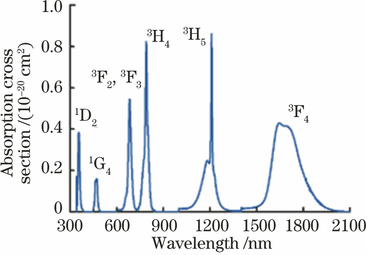
Fig. 1. Absorption cross section of Tm3+-doped glass
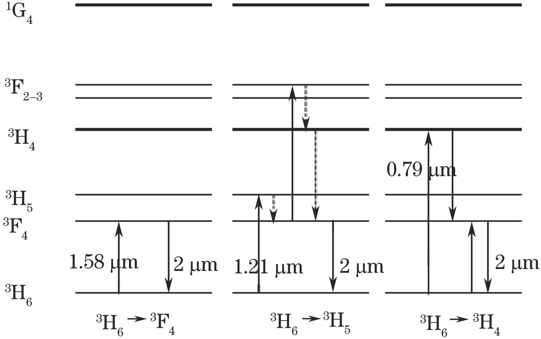
Fig. 2. Schematic of the energy-level transition for Tm3+-doped silica
Fig. 3. Slope efficiency obtained for 793 nm pumped TDF as a function of the Tm3+ doping concentration
Fig. 4. Cross section of the double-clad single-mode TDF
Fig. 5. Cross section and refractive index profile of the triple-clad TDF
Fig. 6. System configuration of high-power TDFL
Fig. 7. Fiber laser output power versus launched pump power
Fig. 8. System configuration of the high-power all-fiberized TDFL
Fig. 9. System configuration of the 227-W high-power all-fiberized TDFL
Fig. 10. System configuration of the high-power all-fiberized TDFL
Fig. 11. (a) Master oscillator and (b) power amplifier of high-power widely tunable TDFL
Fig. 12. System configuration of ultrahigh-efficiency and high-power TDFL
Fig. 13. Fiber laser output power versus launched pump power
Fig. 14. System configuration of high-power, single-frequency, single-polarization TDFL
Fig. 15. (a) Pre-amplifying part and (b) main-amplifier of the high power single-frequency Tm-doped all-fiberized TDFL
Fig. 16. (a) Master-oscillator and (b) power-amplifier of high-power, narrow linewidth, all-fiberized TDFL
Fig. 17. System configuration of high power all-fiberized TDFL
Fig. 18. Output power versus pump power for the two-tone configuration (green-dash) and single-tone (blue) direct amplification of 2130 nm
Fig. 19. Experimental setup of high power narrow spectral bandwidth all-fiberized TDFL
Fig. 20. System configuration of MW-level peak power TDFL
Fig. 21. System configuration of 4 MW peak power CPA system
Fig. 22. Experimental setup of 2 GW peak power CPA system
Fig. 23. Experimental setup of 4 GW peak power pulse compression system
Fig. 24. System configuration of high-power, polarized, all-fiberized picosecond pulsed TDFL
Fig. 25. System configuration of high average power repetition-rate-switchable all-fiberized TDFL
Fig. 26. Seed pulse evolution with pump power at the pump pulse width of 50 ns and repetitionrate of 200 kHz

Set citation alerts for the article
Please enter your email address
© Copyright 2018-2021 | Chinese Laser Press. All Rights Reserved 沪ICP备15018463号-20