• Chinese Optics Letters
  • Vol. 21, Issue 6, 060604 (2023)
Jian Zhou1, Xuelan He1、*, Hongzhou Chen1, Ziyang Xiong1, Jing Yang1, Chunying Guan1、**, and Libo Yuan2
Author Affiliations
  • 1Key Laboratory of In-fiber Integrated Optics, Ministry of Education, Harbin Engineering University, Harbin 150001, China
  • 2Photonics Research Center, Guilin University of Electronics Technology, Guilin 541004, China
  • show less
    DOI: 10.3788/COL202321.060604 Cite this Article Set citation alerts
    Jian Zhou, Xuelan He, Hongzhou Chen, Ziyang Xiong, Jing Yang, Chunying Guan, Libo Yuan. Vector bending sensor based on chirped long-period grating with off-axis micro-helix taper[J]. Chinese Optics Letters, 2023, 21(6): 060604 Copy Citation Text show less
    (a) Schematic diagram of the micro-helix taper-CLPG. (b) Schematic diagram of the grating fabrication process. (c) Microscopic image of the off-axis micro-helix taper.
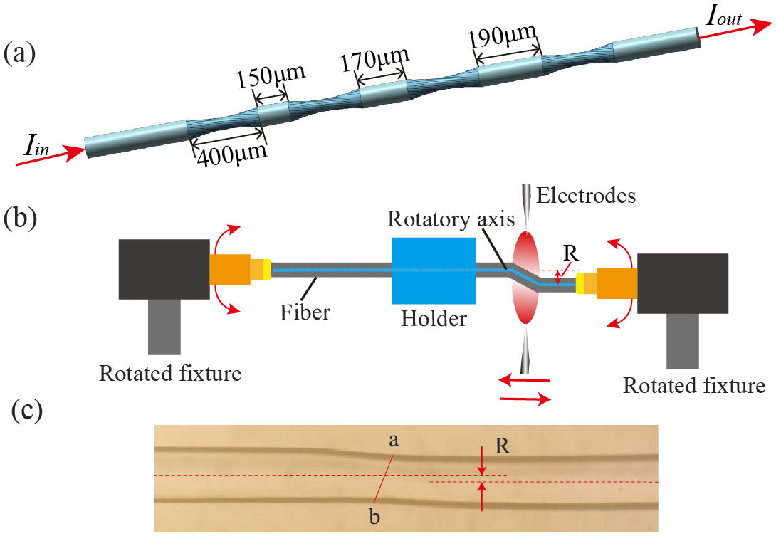
    Fig. 1. (a) Schematic diagram of the micro-helix taper-CLPG. (b) Schematic diagram of the grating fabrication process. (c) Microscopic image of the off-axis micro-helix taper.
    Intensity distributions along the propagation direction. The chirped structure with different off-axis twisted radii. (a) 1 µm, (b) 3 µm, and (c) 5 µm. (d) The non-chirped structure (R = 3 µm).
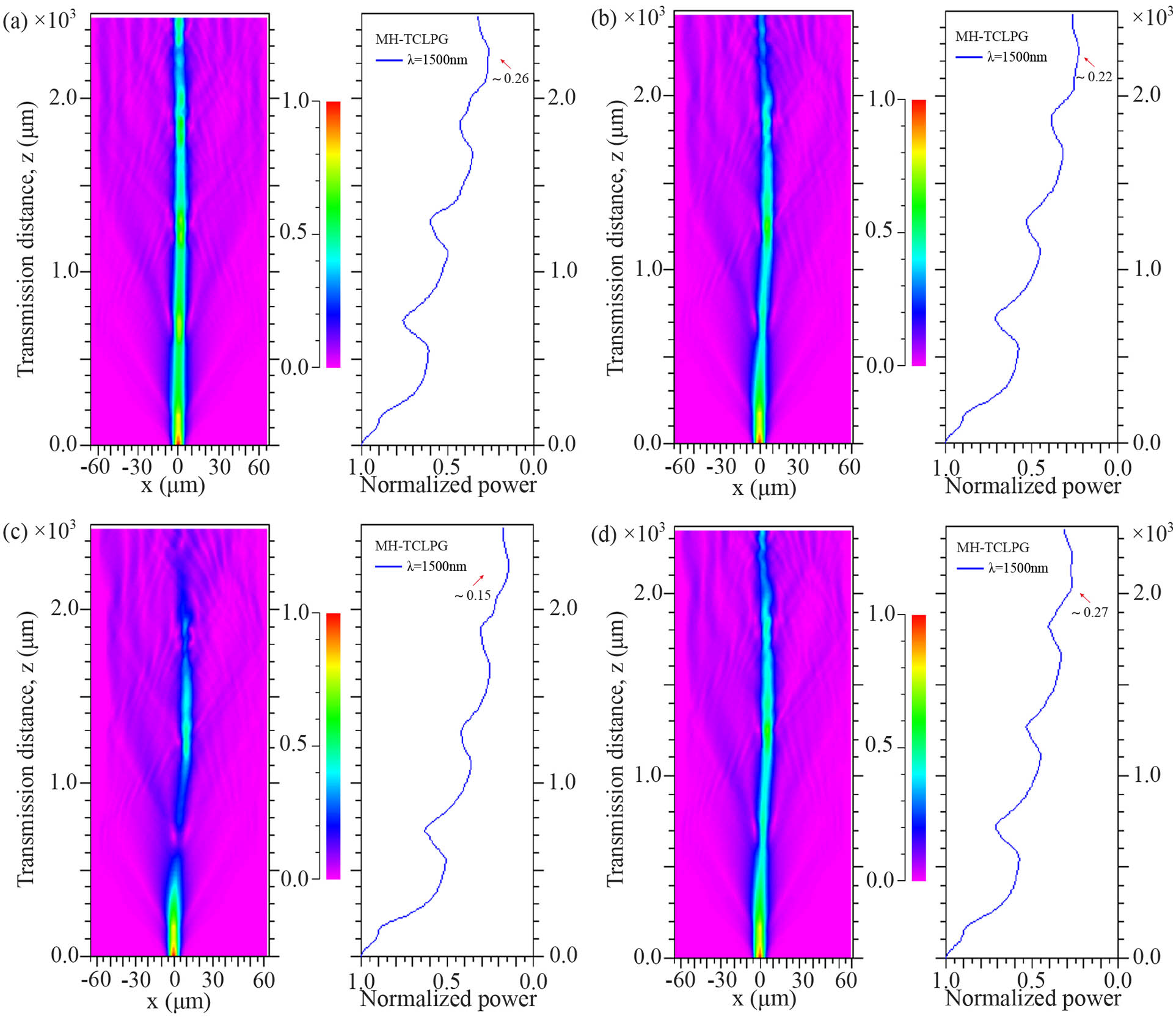
    Fig. 2. Intensity distributions along the propagation direction. The chirped structure with different off-axis twisted radii. (a) 1 µm, (b) 3 µm, and (c) 5 µm. (d) The non-chirped structure (R = 3 µm).
    (a) The cross section of a helical core fiber. (b) The equivalent cross section of the fiber bent in the radius direction axis.
    Fig. 3. (a) The cross section of a helical core fiber. (b) The equivalent cross section of the fiber bent in the radius direction axis.
    Diagram of a curved coordinate system. The section diagram of the bending direction with (a) minimum and (b) maximum refractive index variation.
    Fig. 4. Diagram of a curved coordinate system. The section diagram of the bending direction with (a) minimum and (b) maximum refractive index variation.
    (a) Measured transmission spectra of the CLPG with different torsional radian values. The mode field patterns at (b) 1441.2 nm and (c)1580.4 nm.
    Fig. 5. (a) Measured transmission spectra of the CLPG with different torsional radian values. The mode field patterns at (b) 1441.2 nm and (c)1580.4 nm.
    Spectral evolution of dip A for different bending directions. (a) 0°, (b) 90°, (c) 180°, and (d) 270°. (e) The wavelength of dip A as a function of the curvature for different bending directions.
    Fig. 6. Spectral evolution of dip A for different bending directions. (a) 0°, (b) 90°, (c) 180°, and (d) 270°. (e) The wavelength of dip A as a function of the curvature for different bending directions.
    Spectral evolution of dip B for different bending directions. (a) 0°, (b) 90°, (c) 180°, and (d) 270°. (e) The wavelength of dip B as a function of the curvature for different bending directions.
    Fig. 7. Spectral evolution of dip B for different bending directions. (a) 0°, (b) 90°, (c) 180°, and (d) 270°. (e) The wavelength of dip B as a function of the curvature for different bending directions.
    Bending sensitivity of grating as a function of the rotational angle for (a) dip A and (b) dip B. Insets: diagram of the bending angle.
    Fig. 8. Bending sensitivity of grating as a function of the rotational angle for (a) dip A and (b) dip B. Insets: diagram of the bending angle.
    The wavelength of the dip as a function of the curvature for bending directions 0°, 90°, 180°, and 270°.
    Fig. 9. The wavelength of the dip as a function of the curvature for bending directions 0°, 90°, 180°, and 270°.
    The temperature responses of dips A and B.
    Fig. 10. The temperature responses of dips A and B.
    StructureMax SensitivitySize (mm)Range (m−1)DirectionRef.
    MMF-HCF-MMF−17.28 dB/m−12.51.84–2.94Insensitive[16]
    ECLFBG−0.0609 nm/m−12.00–15Sensitive[17]
    SMF-MCF-SMF−2.42 nm/m−141.50–1.739Insensitive[18]
    HLPFG-SMF1.94 nm/m−115.70–9.06Insensitive[19]
    Micro-holes LPFG−5.198 dB/m−15.70–0.77Insensitive[20]
    GI-MMF-EULPFG−2.25 nm/m−113.60–1.274Insensitive[21]
    PMF-LPFG−13.38 nm/m−14.80–1.86Sensitive[22]
    Ours14.08 nm/m−14.670.128–1.28SensitiveOurs
    Table 1. Comparison of Different Bend Sensors
    Jian Zhou, Xuelan He, Hongzhou Chen, Ziyang Xiong, Jing Yang, Chunying Guan, Libo Yuan. Vector bending sensor based on chirped long-period grating with off-axis micro-helix taper[J]. Chinese Optics Letters, 2023, 21(6): 060604
    Download Citation