Vector bending sensing has been consistently growing in many fields. A low-cost and high sensitivity vector bending sensor based on a chirped long-period fiber grating (LPFG) with an off-axis micro helix taper is proposed and experimentally demonstrated. The grating is composed of several sections of single-mode fiber with gradually larger lengths, and the off-axis micro helix tapers with fixed lengths when they are fabricated by using the arc discharge technology. The large refractive index modulation in the micro-helix taper greatly reduces the sensor size. The total length of the sensor is only 4.67 mm. The micro-helix taper-based LPFG can identify the bending direction due to the asymmetric structure introduced by the micro helix. The experimental results show that the transmission spectra of the sensor have distinct responses for different bending directions, and the maximum bending sensitivity is 14.08 nm/m-1 in the range from 0.128 m-1 to 1.28 m-1. The proposed bending sensor possesses pronounced advantages, such as high sensitivity, small size, low cost, and orientation identification, and offers a very promising method for bend measurement.
Bending measurement is of great significance in the fields of civil engineering, machinery manufacturing, and aerospace[1–3]. Optical fiber bending sensors have the advantages of compact structure, anti-electromagnetic interference, and high sensitivity. The transmission spectrum of a long-period fiber grating (LPFG) is sensitive to bending, and some bending sensors based on LPFG have been successfully realized. It is necessary for a sensor to recognize the bending orientation in the monitoring of building walls, bridge piles, and road surfaces. However, traditional LPFGs are usually axisymmetric about the transmission axis, so it is difficult to use them in identifying bending directions[4].
To distinguish bending directions, the LPFG needs to have an asymmetric structure or an asymmetric modulation of the refractive indices of the fiber cladding and core introduced by micro-fabrication technology so that it can respond differently to each bend direction. Some LPFGs based on asymmetric special fibers have been proposed to detect bending orientation. For example, Saffari et al.[5] fabricated an LPFG in a multicore fiber consisting of 120 single mode cores by using UV inscribed technology, and the bending sensitivity is up to . Zhong et al.[6] proposed an LPFG fabricated using a laser in a hollow eccentric fiber. The resonant peak shifts linearly with increasing curvature, but its sensitivity is lower than that of the LPFG in single-mode fibers (SMFs). Jiang et al.[7] experimentally demonstrated an LPFG based on a polarization-maintaining fiber, and the achieved maximum curvature sensitivities are and for the fast and slow axes, respectively. However, the cost of LPFG based on special fiber is expensive. Some SMF-LPFGs can distinguish different bending directions by introducing a V-shaped[8] arc grid with a chirped radius[9], a γ-shaped[10], an arch-shaped[11], a D-shaped[12], or other asymmetric structures. However, the LPFGs with asymmetric structures need to break the fiber’s circular symmetry, and the fabrication process is complex. Meanwhile, asymmetric structures usually require high precision and expensive manufacturing equipment such as a laser. Therefore, a sensor with low cost and high sensitivity for distinguishing bend directions is desired.
In this paper, we propose and experimentally demonstrate a vector bending sensor based on a micro-helix taper-chirped LPG (CLPG). The micro-helix taper-CLPG displays a good directional dependence in the range from to . The bending sensitivities vary from to for different bending directions, and there exists a sinusoidal relationship between the bending sensitivity and the orientation angle. The bending sensitivities are higher than those of most LPFG-based and interferometer-based vector bending sensors. Moreover, the sensor’s temperature responses are also investigated, and the temperature sensitivity is 0.05868 nm/°C.
Sign up for Chinese Optics Letters TOC. Get the latest issue of Chinese Optics Letters delivered right to you!Sign up now
2. Fabrication and Principle
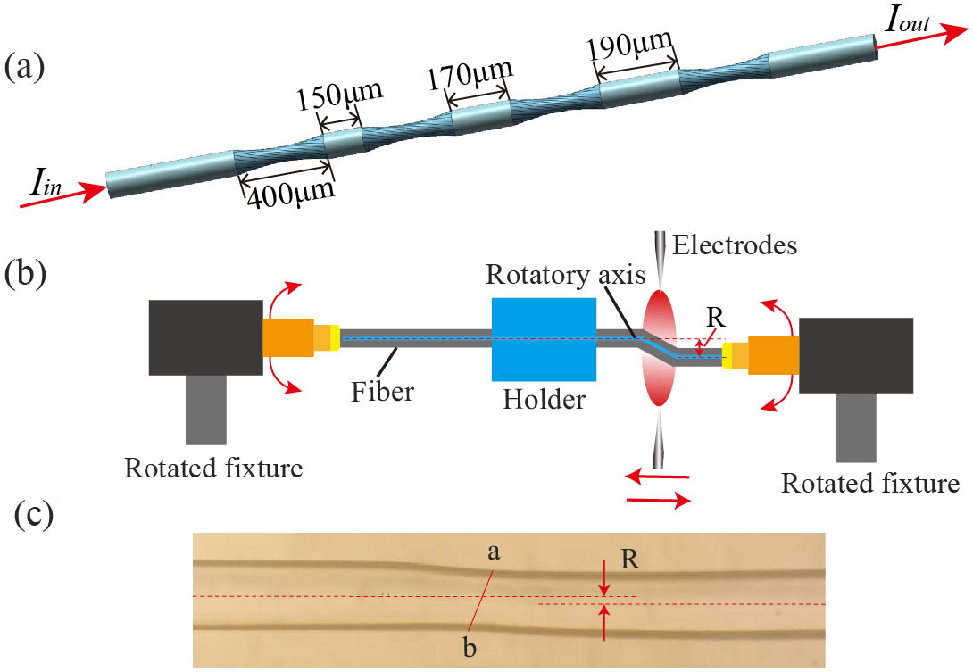
Figure 1(a) shows the schematic diagram of the micro-helix taper-CLPG. Each period consists of an SMF and a micro-helix taper, in which the length of the SMF is chirped with an equidistant chirp length of 20 µm, while the length of the micro-helix taper is fixed. The schematic diagram of the grating fabrication process is shown in Fig. 1(b). Two ends of the SMF [Corning, SMF-28e(R)] were fixed by two rotatable clamps with a division value of 0.05 turns. The rotatable clamps can move left and right. A movable arc discharge from a pair of the electrodes was focused on a spot, in which the diameter depends on the discharge current. The arc and the right 3D translation stage simultaneously moved according to the respective preset displacements during the taper drawing process. Meanwhile, the right rotatable clamp rotates counterclockwise. The arc current is 23.8 mA, and the arc duration is 4.36 s. The displacements of the arc discharge and the right translation stage are 350 µm and 50 µm, respectively. So the total length of the micro-helix taper is 400 µm. The torsional radian value is set to 0.2 turns. The fiber is heated and sustains the tension and torsion from the rotatable clamp, and the micro-helix taper is created. It is necessary to adjust the axial displacement between the holder and right rotator to make a suitable off-axis twisted radius () during the twisting process. The micrograph of the fabricated off-axis micro-helix taper is shown in the inset of Fig. 1(c). The axis symmetry of the fiber is broken due to the torsion. Points a and b [marked in Fig. 1(c)] are the thinnest positions of the top and bottom profiles and are asymmetric at the tapered waist (marked with a red solid line).
Figure 1.(a) Schematic diagram of the micro-helix taper-CLPG. (b) Schematic diagram of the grating fabrication process. (c) Microscopic image of the off-axis micro-helix taper.
The beam propagating method (BPM) is used to simulate the transmission characteristics of the micro helix tapers with different off-axis twisted radii (1 µm, 3 µm, and 5 µm). The arc discharge will reduce the refractive index of the core and increase the refractive index (RI) of the cladding due to the thermal diffusion effect. To simplify the model, the refractive index is assumed to be the same in the entire taper region. The RIs of the core/cladding of the SMF and the micro-helix taper were set to be 1.4682/1.4628 and 1.4661/1.4635, respectively. The core/cladding diameter of the SMF is 8/125 µm, the diameter of the tapered waist is 120 µm, and the length of the taper area is 400 µm. The radian value of the micro taper torsion is set to 0.2 turns. Figure 2 shows the light intensity distributions of the chirped grating with different off-axis twisted radii at the wavelength of 1500 nm along the transmission direction. It can be seen from Figs. 2(a)–2(c) that as increases, the energy coupling from the core into the cladding is faster. When is larger than 5 µm, the energy loss is relatively large, and the spectrum attenuation is serious. Therefore, 3 µm is selected in our work. To compare the intensity distribution of the grating with the uniform period, the off-axis twisted radius of 3 µm is also given [Fig. 2(d)]. The chirped grating is more likely to excite the cladding modes in the same grating length by comparing the non-chirp structure [Fig. 2(d)] with the chirp structure [Fig. 2(b)]. Therefore, the chirp structure can reduce the number of periods to obtain a shorter sensor length.
Figure 2.Intensity distributions along the propagation direction. The chirped structure with different off-axis twisted radii. (a) 1 µm, (b) 3 µm, and (c) 5 µm. (d) The non-chirped structure (R = 3 µm).
When the grating is bent, the effective RI of the higher-order modes in the cladding will change, which leads to changes in the center wavelength and in the depth of the resonance peak. The wavelength shift can be expressed as[13]where is the curvature. The wavelength shift is mainly caused by the change of the grating period and the refractive index. The SMF helical structure can be considered as a deformation of a straight circular core[14], as shown in Fig. 3(a). We suppose that the helical part consists of numerous segments of the eccentric core rotating by the experimental preset angle around the center, and the offset () is very small. The fabricated CLPG has eight micro-helix tapers, each of which is twisted 0.2 turns. The first five micro-helix tapers form a circle and can be regarded as a kind of core-symmetrically distributed multicore fiber. In the multicore fiber, the fiber core inside the neutral surface of the fiber bending is compressed, and the fiber core outside the neutral surface is stretched. The contribution of the first five micro-helix tapers to the orientation identification is ignored. Therefore, the latter three micro-helix tapers mainly contribute to the bending orientation identification. The equivalent fiber structure of the last three periods is shown in Fig. 3(b). Since the last three periods have a total torsion of 216°, there is no eccentric core in the remaining region of 144°. The bending orientation angle is defined as the angle of the bending direction with respect to axis. Suppose that the is the angle of any eccentric core with respect to the axis [as shown in Fig. 3(b)]. For the single eccentric core fiber, the change of the refractive index of the optical fiber caused by the axial strain () due to bending can be expressed as[15]where is the photoelastic constant, , is the bending radius, and is the distance from the eccentric core to the neutral plane. The change of the refractive index introduced by bending can be expressed as where . It is substituted into Eq. (3),
Figure 3.(a) The cross section of a helical core fiber. (b) The equivalent cross section of the fiber bent in the radius direction axis.
As can be seen from Fig. 3, this is a mirror symmetry structure, so we only study the structure on the left side. The range of is 0°–108° and that of is 0°–180°. Considering Eq. (3) and Fig. 3, according to the integration theorem, Eq. (4) can be transformed into the following form:
According to Eq. (6), for the left half of the structure, when is 54°, the refractive index change reaches the maximum value; while is 144° the change is the minimum. According to Eq. (4), its value is the integral area of the multi-core track to the neutral plane. The shaded areas are shown in Fig. 4. The shadow area is minimum when the line with the first and last eccentric core [marked M and N in the Fig. 4] is parallel to the bending direction [shown in Fig. 4(a)], and it reaches the maximum when M and N are perpendicular to the bending direction [shown in Fig. 4(b)].
Figure 4.Diagram of a curved coordinate system. The section diagram of the bending direction with (a) minimum and (b) maximum refractive index variation.
The transmission spectra of the micro-helix taper CLPG with torsional radian values of 0.1 turns, 0.2 turns, and 0.3 turns are shown in Fig. 5(a). When the torsional radian value is 0.1 turns, the resonance peak cannot be observed. When the torsional radian value is 0.3 turns, the loss introduced by the micro-helix tapers is about 20 dB, which is too large for practical applications. So the torsional radian value is set to 0.2 turns in the experiment. Two dips, A and B, are generated at the wavelength of 1441.2 nm and 1580.4 nm. The near-field distributions at the wavelengths of two dips are shown in Figs. 5(b) and 5(c). It can be clearly seen that the resonant dips are attributed to the coupling between the fundamental mode and the and cladding modes. This anti-symmetric mode is sensitive to the bending direction. We have fabricated several sensors under the same fabrication condition, and the measured transmission spectra have good reproduction. Therefore, the micro-helix taper CLPG can be easily fabricated repeatedly using the proposed technique.
Figure 5.(a) Measured transmission spectra of the CLPG with different torsional radian values. The mode field patterns at (b) 1441.2 nm and (c)1580.4 nm.
The bending responses of the grating were investigated. Before the bending measurement, the grating was carefully adjusted to a position where the wavelength moves more obviously due to the bending, so the fiber was rotated 54° clockwise by two rotatable clamps. Then, by slightly adjusting the rotatable clamp and monitoring the wavelength shift with bending, the bending direction corresponding to the largest wavelength shift was found. Such a direction was defined as 90° bending direction; then the CLPG was rotated 90° anti-clockwise by rotating the rotatable clamp, and such a direction was defined as 0° bending direction, as shown in Fig. 4. The direction-dependent bending responses of the CLPG for dips A and B are shown in Figs. 6 and 7, respectively. Figures 6(a)–6(d) and 7(a)–7(d) show spectral evolutions of dips A and B as the curvature increases from to with a step of at the 0°, 90°, 180°, and 270° bending directions, respectively. The arrows point to the directions of increasing curvature. The bending direction of the sensor is changed from 0° to 330° with a step of 30°. The wavelength responses of dips A and B for different bending directions are shown in Figs. 6(e) and 7(e), respectively. To avoid the error caused by the non-axial symmetry of the measuring system to the initial point, we start recording from the second experimental data. From Figs. 6(e) and 7(e), the wavelength changes with the curvature in each direction and has a good linearity. It can be seen from Fig. 3 that the eccentric cores are symmetrically distributed on both sides of the neutral plane, and the refractive index change is minimal at the bending directions of 0° and 180°, when all eccentricities are distributed on the same side of the neutral plane, and the refractive index change reaches its maximum. Figures 6(e) and 7(e) show that the bending sensitivities of dip A are at 90° and at 270°, while those of dip B are at 90° and at 270°. The small sensitivity difference between the opposite bending directions is mainly due to the bending direction inaccuracy that is caused by the fiber rotators.
Figure 6.Spectral evolution of dip A for different bending directions. (a) 0°, (b) 90°, (c) 180°, and (d) 270°. (e) The wavelength of dip A as a function of the curvature for different bending directions.
Figure 7.Spectral evolution of dip B for different bending directions. (a) 0°, (b) 90°, (c) 180°, and (d) 270°. (e) The wavelength of dip B as a function of the curvature for different bending directions.
Figure 8 indicates bending sensitivities as a function of the bending directions of dips A and B, respectively. There is a sinusoidal relationship between the curvature and the bending sensitivity. These are in good agreement with Eq. (6), which indicates that the sensor has a good repeatability.
Figure 8.Bending sensitivity of grating as a function of the rotational angle for (a) dip A and (b) dip B. Insets: diagram of the bending angle.
In order to further verify the previous theoretical analysis, we used the same manufacturing parameters to make an LPFG with a total torsion angle of 360°. The bending characteristics at four directions (0°, 90°, 180°, and 270°) are shown in Fig. 9. The bending sensitivities are , , , and at 0°, 90°, 180°, and 270°, respectively. The experimental results show that when bending occurs in different directions, the dip wavelength has a blue shift, which indicates that the sensor with a total torsion angle of 360° does not have the ability of direction recognition.
Figure 9.The wavelength of the dip as a function of the curvature for bending directions 0°, 90°, 180°, and 270°.
Table 1 lists the comparison of performances of the proposed micro-helix taper-CLPG with other reported sensors. The micro-helix taper-CLPG has a high bending sensitivity as well as a direction-dependent property, and its sensitivity is higher than those of most LPG-based and interferometer-based vector bending sensors. The dynamic range of bending measurement is . Moreover, the proposed sensor is manufactured only by cheap SMF and has a small size.
The temperature responses of the two dips of the grating were tested. The dependence of the resonance wavelength on the temperature is shown in Fig. 10. The insets are the spectral evolutions of the resonance dips with the increasing temperature. When the temperature increases from 20°C to 80°C, dips A and B shift to the longer wavelength. The wavelength shift has a good linearity with the temperature. The sensitivities of dips A and B are 58.7 pm/°C and 75.6 pm/°C, respectively.
Figure 10.The temperature responses of dips A and B.
Since dip A and dip B have different response characteristics for bending and temperature , simultaneous measurements of the bending and the temperature can be achieved, and thus the temperature crosstalk can be removed. Based on the obtained bending and temperature sensitivities, the demodulation matrix is established and is expressed as where , , , and are the bending and temperature sensitivities of dips A and B, respectively.
4. Conclusion
In summary, a novel vector bending sensor with a high sensitivity based on the micro-helix taper-CLPG is experimentally demonstrated. The micro-helix taper and SMF of chirp length form a CLPG with an asymmetric structure, leading to direction-dependent spectral responses. The experimental results show the bending sensitivities vary from to for different bending directions in the curvature range from to , and there exists a sinusoidal relationship between the bending sensitivity and the bending direction. Due to the advantages of sensitivity and the ability to identify direction, the proposed sensor has potential application prospects in bend detection fields.