An PAN, Yuting GAO, Aiye WANG, Huiqin GAO, Caiwen MA, Baoli YAO. High-throughput Full-color Fourier Ptychographic Microscopy for the Next Generation of Digital Pathologic Imager and Analyser(Invited)[J]. Acta Photonica Sinica, 2022, 51(7): 0751408
Copy Citation Text
Fourier Ptychographic Microscopy (FPM) is a promising computational imaging technique, which tackles the intrinsic trade-off between high resolution and large wide Field Of View (FOV) with a combination of Synthetic Aperture Radar (SAR) and optical phase retrieval. In brief, an LED array beneath the microscope provides illumination of the object from different incident angles. The range of light that can be collected is determined by the Numerical Aperture (NA) of the objective, while parts of the scattering light with a high-angle illumination can also be collected because of light-matter interaction. The low resolution intensity images recorded at each illumination angle are then synthesized in the Fourier domain, thus the object’s high-frequency information can be modulated into the passband of the objective. After an iterative phase reconstruction process, the synthesized information generates a high resolution object image including both intensity and phase properties. Additionally, it preserves the original large FOV as a low-NA objective is used to stitch low resolution images together. Given its flexible setup without mechanical scanning and interferometric measurement, FPM has developed rapidly, which not only acts as a tool to obtain both HR and large FOV but is also regarded as a paradigm to solve a series of trade-off problems, say, the trade-off between angular resolution and spatial resolution in light field imaging. And it may inspire to solve the trade-off between spectral resolution and spatial resolution in imaging spectrometer in the future.In this paper, we comprehensively summarized the development trend of FPM technique in 9 aspects, including high-precision imaging, high-throughput imaging, high-speed or single shot imaging, 3D or tomography imaging, mixed state decoupling, spectral dimension (color imaging to hyperspectral imaging), high dynamic range, system extension, and typical applications. Among them, digital pathology is one of the earliest and the most successful applications of FPM. Distinguished from other reviews, we focused on introducing the development process and recent advances in the direction of digital pathology, and divided it into “0-1”, “1-10”, and “10-100” three periods and several stages. Several typical results are also provided. Specifically, the “0-1” refers to the birth of FPM, which breaks the mutual restrictions between FOV and spatial resolution. The “1-10” refers to the exploration period, where the accuracy and stability, limits and bottlenecks, and the efficiency of FPM have been successively discussed and improved. The stage of “10-100” refers to the industrialization period. During this period, researchers focus on market-oriented requirements including acquisition and analysis of color, since full-color imaging is of critical importance for analyzing labeled tissue sections.We point out that FPM has entered the industrialization stage of “10-100” in this application direction.The current task is to build a prototype or product based on FPM. We expect that the product can obtain a spatial resolution of around 200 nm~1 000 nm, a FOV of around 10 mm (2× objective) or 5 mm (4× objective) diameter full-color FPM reconstructed image within 4 s at the DOF of around 0.3~0.5 mm stably and efficiently. We estimate that it can be capable of automation and batch scanning within the next 1~2 years. We analyzed the industry development situations of digital pathology and related market requirements, and discussed the potential of FPM for large-scale socio-economic benefits. We demonstrated that the full-color images with high quality and content and quantitative phase images produced by FPM may play a role of promotion in wide fields, including intraoperative pathology, quantitative Artificial Intelligence (AI) diagnosis, three-dimensional reconstruction, telepathology, teaching and standardized industry criteria. It should also be clarified that as a typical interdisciplinary field, even if the instrument is successfully invented, it only solves issues in the imaging section of the whole process of digital pathology, and there still remain a series of tough tasks to complete. We discussed and classified related scientific problems, technical problems, engineering problems, and industrial problems in detail, whose successful and perfect resolution relies on joint efforts of various parties and constructive introduction of several potential approaches. By combining the FPM solution with the upstream and downstream advanced methods, including the virtual staining, multimodal fusion imaging, label-free observation in situ, non-destructive three-dimensional reconstruction, preliminary screening, and recognition with AI, etc., we believe that the industry problems will eventually be overcome or alleviated.
Pathology is a bridge between basic research and clinical applications. Analyzing pathology slides using an optical microscope remains as the gold standard in diagnosing a large number of diseases including almost all types of cancers. Compared with the department of clinical laboratory and picture archiving in a typical hospital of China as shown in Table 1,the pathologic diagnosis can obtain definitive diagnosis,but it requires 5~10 workdays to get the final reports. Note that intraoperative pathology is quite sensitive to time. Given the fact that,on the one hand,the pathology department has higher requirements for personal experience and takes a long time to train pathologists. And currently,there is a relative shortage of pathologists worldwide. On the other hand,it has less automatic and digital equipment,which causes that the diagnostic procedures are divided into multiple steps that are conducted by different pathologists and also the department is labor-intensive. These difficulties synthetically result in the long-time diagnosis.
Departments
Checklist
Required time
Type of diagnosis
Clinical laboratory
Biochemistry & Immunity
Hepatic and renal function
2 hours
Deductive Diagnosis
Blood glucose,lipids,electrolytes
Routine immunization
Luminescence
Tumor markers
On that day
Thyroid function
Gonadal hormone
Bacteria
Smear and staining
On that day
Bacterial culture
4 hours
Picture archiving
X-ray
1 hours
Ultrasound
Magnetic Resonance Imaging(MRI)
Pathology
Conventional small sample
3 days
Definitive Diagnosis
Large samples of surgical removal
5 days
Immunohistochemistry,molecular pathology
7~10 days
Table 1. The information of checklist and its required time at a typical hospital in China
Specifically,traditional pathology has four main steps:sample preparation,imaging,analysis,and report output. At the heart of these steps is the imaging step,where the imaging quality directly affects the subsequent judgments. Currently,traditional pathology still relies on observation through a microscope eyepiece with the naked eyes. It is necessary to switch back and forth between objective lens with different magnification and shift Field Of View(FOV)to detect pathological features. The operation may be easily disrupted,and the features may be easily omitted. It is also highly subjective as different pathologists may arrive at different conclusions or the same pathologist may give different conclusions at different time points. For a piece of tissue with hundreds to thousands of slices,undoubtedly,there is a heavy workload and would be low efficiency[1-2].
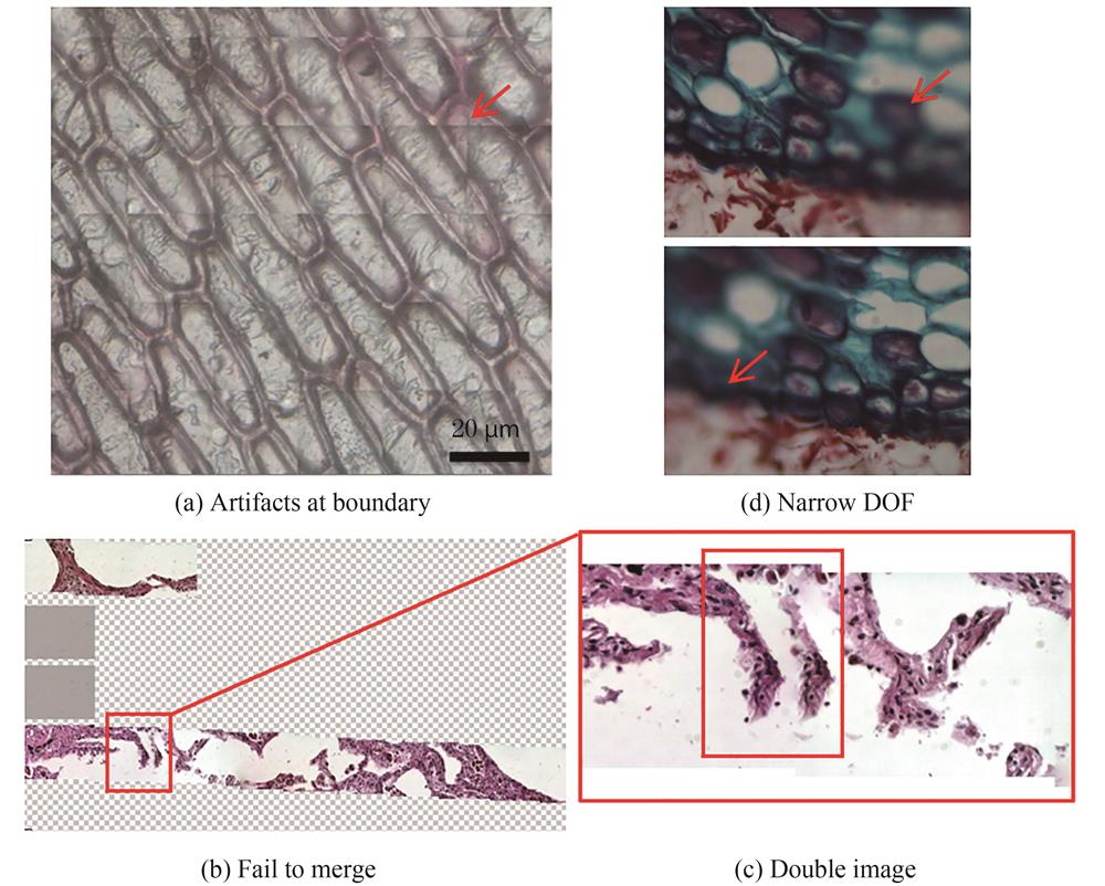
With the rapid development of computational power and the digital trend of picture achieving,communication and telediagnosis,modern digital pathology adopts digital imaging and mechanical scanning to obtain High Resolution(HR)first and then large FOV so as to achieve full FOV imaging of a single slice,termed Whole Slide Imaging(WSI)system[1-2]. This kind of instrument is the so-called digital pathology scanner,while it still has to overcome four intrinsic defects. First,the imaging quality and success rate is not high enough:due to the drift of electronic devices,the stitching boundary is prone to artifacts(Fig. 1(a)). To overcome it,an elaborate registration or feature matching algorithm is required. However,for sparse samples,due to a large amount of blank area and lack of adjacent features,they may not be spliced(Fig. 1(b)),and the feature matching errors tend to cause double image(Fig. 1(c)). As a result,the success rate is directly related to the kind of samples and is relatively low due to those artifacts. Second,the application scenarios are limited:Due to the narrow Depth Of Field(DOF)of a high Numerical Aperture(NA)objective,it is limited to histopathology or hematology and cannot be applied in cytopathology for a certain thickness(Fig. 1(d)). Even it may also fail due to air bubbles. Thus,axial scanning may be needed for conventional WSI system,adding another degree of complexity of data handling to the system. Third,the efficiency is relatively low:Among the four-step workflow of translation,autofocusing,imaging and stitching,the translation and autofocusing need to be performed repeatedly at high speed,while the imaging time accounts for a small proportion and the detector is idling for most of the time. Fourth,the instrument is expensive:Precise mechanical control and pulsed illumination are often needed to shorten the acquisition time. The resultant systems are expensive and of high maintenance. Considering all the issues above,digital pathology is not universally accepted by pathologists currently and is only regarded as a supplementary tool in limited fields like research,teleconsultation and etc.
Figure 1.The intrinsic drawbacks of conventional digital pathologic scanners
Fourier Ptychographic Microscopy(FPM)[3-10] was invented in 2013 by introducing the concept of ptychography[11-14] into the reciprocal(Fourier)space,which breaks the trade-off between large FOV and HR with a combination of synthetic aperture radar[15-16] and optical phase retrieval[17-18]. On the hardware side,the condenser of conventional optical microscopy is replaced by a cheap LED array,which is still compatible with modern microscopes. And the LED elements are lighted up sequentially to achieve the synthetic aperture and resolution improvement. In theory,the objective can only collect light ranging from a certain angle,characterized by the NA. However,parts of the scattering light with a high-angle illumination can also be collected because of light-matter interaction. The sample's high-frequency information can be modulated into the passband of the objective lens. Instead of conventionally stitching small HR image tiles into a large FOV,FPM uses a low NA objective innately with a large FOV to stitch together Low Resolution(LR)images in Fourier space and finally obtain HR images. Compared with conventional digital pathology,firstly,no mechanical scanning is required for the angle-scanning scheme,therefore,the stitching artifacts,double images,splicing failure problems are all solved fundamentally,and the image quality is guaranteed. Secondly,the detector would not be idling and keeps working,therefore,the FPM solution is a high-throughput technique(~1 gigapixels). Thirdly,the low NA objective has an innate long DOF and working distance,and the DOF can also be digitally extended to more than 300μm[3] according to the principle of coherent imaging. Note that the slicer can cut the sample up to 100 μm,which is fully covered by the DOF so that it is not easy to lose focus. Fourthly,the aberration can be digitally recovered and compensated. Fifthly,additional quantitative phase information can be provided and used for quantitative biology. In a nutshell,the FPM solution ideally solves the above-mentioned problems of conventional digital pathology and offers some unique advantages that are not available previously.
Currently,FPM has been written into the book of the Introduction to Fourier Optics(4th edition)by Goodman[19]. Given its flexible setup without mechanical scanning and interferometric measurement,FPM has improved rapidly,which not only acts as a tool to obtain both HR and large FOV but is also regarded as a paradigm to solve a series of trade-off problems,e.g.,the trade-off between angular resolution and spatial resolution in light field imaging[20]. And it may inspire to solve the trade-off between spectral resolution and spatial resolution of the imaging spectrometer in the future. The trend of FPM on several aspects is illustrated in Fig. 2 including high-precision imaging[21-38],high-throughput imaging[39-43],high-speed and single shot imaging[44-58],three-dimensional(3D)imaging and tomography[59-64],mixed-state decoupling[65-71],wavelength diversity[72-77],high dynamic range imaging[78],system extension[79-101] and several typical applications in label-free Quantitative Phase Imaging(QPI)[102-107],cell culture and drug screening[108-109],Circulating Tumor Cell(CTC)analysis[110],retina imaging[111],wafer detection[112],optical cryptosystem[113-114],and remote sensing[16,115-116],etc. Among these 9 aspects,the first 5 aspects and parts of the applications can be referred to those comprehensive reviews of Refs.[8,9]in detail. The wavelength,dynamic range and system extension are new trends. Some results indicate that the wavelength multiplexing FPM achieves the spectral resolution of around 2 nm and develops towards hyperspectral imaging[77]. The FPM algorithm can also extend the dynamic range of single photon avalanche diode array[78]. In terms of the system extension,the light source can be changed to laser array or laser and 2D Galvo mirror[79-80],LED and 2D Galvo mirror[81],and liquid crystal display[82],etc. The reflective construction offers possibilities for optical remote sensing[16,116] and optical detection[112]. Benefit from the aberration removal of FPM,the single lens design makes the optical system more compact. And the aperture scanning scheme completely changes the thinking set of multi-angle scanning scheme in FPM and provides the abilities of DOF extension[83-85] and incoherent FPM[111]. Combined with the speckle illumination,the FPM can broaden the scene of applications and achieve the scattering imaging and multimodal imaging.
In this paper,we focused on reviewing the application of FPM in digital pathology,since the digital pathology is the initial application area of FPM,and it may be one of the most successful applications of FPM currently and develops rapidly. The origin and basic principle of FPM are introduced in Section 1 in brief. We emphatically review its multiple stages and significant advances toward the next generation of digital pathologic imager and analyzer in Section 2 and point out that it has entered the industrialization stage of “10-100” in this direction of digital pathology. In Section 3,we discuss its potential for large-scale economic benefits and its impacts on both upstream and downstream ecology. The high-quality imaging results of FPM will significantly benefit the subsequent judgement and analysis,and will provide high-quality data for auxiliary diagnosis via Artificial Intelligence(AI). Finally,we summarize our topic and put forward some unsatisfactory points at present and give prospects for the future in Section 4.
1 Origin and principle
The name of FPM is taken from ptychography. Similar to the terminology of holography,“holo” comes from “oλo” in Greek and means “all”,namely the hologram contains all the wavefront information including both amplitude and phase. “Ptycho” comes from the Greek word “πτυξ” that means “to fold”[117],because the diffraction pattern is a convolution between the Fourier transform of a finite illumination function and the Fourier spectrum of the object,which is illustrated in Fig. 3(a). At the beginning,ptychography was proposed in 1969 to solve the phase problem in electron diffraction measurement with only one intensity image and is one kind of the methods of Coherent Diffraction Imaging(CDI)[117]. However,the phase retrieval with a single diffraction pattern is sensitive to the noise and is difficult to converge or fall into local minimum[18]. With the development of light sources,detectors,computational power and advanced algorithms[35,118-128],FAULKNER H M L et al. in 2004[11,118] modified it to record multiple diffraction patterns through the scan of an overlapped localized illumination on an extended object,which extended its capabilities to image non-crystal objects and also applied it to X-ray[129-140] and optical imaging setups[70,141-144]. The overlapping regions of adjacent illuminated spots are a coherent superposition,which locks the phase relationship at different positions of the sample and objectively plays the role of the reference beam in the holography that thus no reference arm is required practically[8]. This set of diffraction patterns is then used to invert the diffraction process and retrieve the complex sample profile. Compared with the hypostasis of vector addition in interferometry,the keystone of diffraction methods relies on vector convolution.
Figure 3.The comparisons between ptychography[102],FPM[127],and Structured Illumination Microscopy(SIM)
Before the introduction of ptychography,CDI and Scanning Transmission X-ray Microscopy(STXM)evolved quite independently and achieved good results in their own field[140]. The major drawback of CDI is the requirement of crystal or quasicrystal samples,which makes the sample preparation hard and limits its applications. While in STXM,the problem is that the spatial resolution is limited by the size of Fresnel zone plate,which can hardly exceed 10 nm due to the fabrication issues. Ptychography with brilliant X-rays emerged in the late 2 000 s as a method that finally enabled a marriage between the advantages of STXM and CDI,and it overcomes the biggest disadvantages of both techniques[140].
In the case of ptychography as shown in Fig. 3(a),the object support constraints for phase retrieval are imposed by the confined illumination beam in the spatial domain. The reciprocal support constraints are those diffraction patterns in the frequency domain. As such,the sample or probe must be mechanically scanned using the desired FOV. With FPM as shown in Fig. 3(b),the object support constraints are given by the confined Coherent Transfer Function(CTF)in the Fourier domain and the reciprocal support constraints are those LR images in the spatial domain. In this regard,FPM acts as the Fourier counterpart to ptychography,justifying its name. In fact,the LR images of FPM are equivalent to the 90o rotation of ptychographic diffraction patterns in the phase space of 4D Wigner distribution function[145],which means that a linear transformation mathematically links these two datasets. And the concept of FPM can also trace its roots back to the relationship between the reciprocal system established in 1994 by LANDAUER M N for electron microscopy[146] and the Imaging Interferometric Microscopy(IIM)established by SCHWARZ C J et al. in 2003[147-148]. Still,the methods only succeeded in experimenting about two decades later because of the development of light sources,detectors,computational power and advanced algorithms. Thus,such computational imaging techniques are also gaining increasing attention[8-9,149-152].
In a typical implementation(Fig. 3(b)),FPM employs a programmable LED array for illuminating the sample from different incident angles,contributing to relative displacement between the spectrum of the sample and the CTF due to the Fourier translation theorem[19]. A low-NA objective lens is used to acquire the corresponding images. In the reconstruction process,the captured LR intensity images are synthesized in the Fourier space to expand the available bandwidth. The synthesized information is then transformed back to the spatial domain to generate an HR object image containing both intensity and phase properties. By using a low-NA objective lens,FPM retains the large FOV set by the lens. With the aperture synthesizing process,it can generate HR images. As such,it achieves both HR and large FOV at the same time. Compared with conventional scanning WSI systems,no mechanical scanning is needed in FPM. The use of a low NA objective also has the benefit of both a long DOF and a long working distance,thereby addressing the above-mentioned challenges of regular WSI systems in Fig. 1.
Numerically,for each LEDm,n(row m,column n)and its illumination wave vector(kx,m,n,ky,m,n),under the assumption that the incident light is an ideal plane wave and the sample is relatively thin,the transmitted wave field from the sample o(x,y)can be described as ,where o is the sample's transmission function,(x,y)denotes the 2D Cartesian coordinates in the sample plane,j is the imaginary unit. Then the transmitted light field is Fourier transformed to the Fourier plane and multiplied by the pupil function accordingly,which can be represented as ,where P(kx,ky)is the pupil function,which is the coordinate transformation of pupil function p(x,y)in the spatial domain,termed CTF,and acts as a low-pass filter of an imaging system,(kx,ky)denotes the 2D spatial frequency coordinates in the Fourier plane,and F denotes the Fourier transform operator defined by
where the original 2π in the Fourier transform is contained in the 2D spatial frequency coordinates. Afterward,the light field is inverse Fourier transformed to the image plane and the imaging sensor captures an LR intensity image Im,n of the sample,which is given by
where F -1 is the inverse Fourier transform operator,and O is the Fourier spectrum of the object. The incident wave vector(kx,m,n,ky,m,n)can be expressed as
ππ
where(x0,y0)is the central position of each tile after block processing for parallel computation,(xm,n,ym,n)denotes the position of the LEDm,n,λ is the central wavelength,h is the distance between the LED array and sample. Note that the Eq.(3) is not uniform and is related to the specific coordinate system. FPM attempts to eliminate or minimize the variations in amplitude between simulation patterns and captured images iteratively by formulating the following non-convex optimization issue.
To solve this issue,a typical framework of iterative algorithm is given in Fig. 4 that includes 5 steps. 1)Initialize the HR image with interpolation of a LR image. Note that the initial guess can also be random guess and full-one guess. The closer the initial guess is to the truth,the faster the algorithm converges. 2)Generate a LR estimate. 3)Replace the amplitude of LR estimate by the LR intensity measurement. 4)Repeat steps 2-3 for m×n plane wave incidences,then one iteration is completed. 5)Repeat steps 2-4 several times to make the algorithm converge. It is commendable that the FPM framework gracefully solves three significant issues simultaneously:phase recovery,synthetic aperture,and upsampling,while a normal algorithm only solves one thing.
Figure 4.The flowchart of FPM reconstruction algorithm
So far,many classical and widely used algorithms have been reported,including EPRY-FPM[22],Gaussian-Newton[25],Wirtinger flow[26],mPIE[35] and ADMM[38],etc.,which basically adopts this iterative framework. The main differences are that their objective function introduces different regularization terms or adopts the L-1 norm compared with Eq.(4),etc. There is a detailed summary in the Refs.[8,38]and will not be expanded here.
FPM also shares the root with structured Illumination Microscopy(SIM)due to Euler's formula as shown in Fig. 3(c)and is given as follows. The illumination wavefront can have the same effect with a Cosine structured illumination pattern if the two symmetrical light beams and a normal incident beam illuminate the sample simultaneously
where θ1 is a certain incident angle. Since three beam information is mixed together in SIM,it is usually appropriate to capture three phase-shift images and recover the HR image along an axis[153-155]. While in FPM,these three images have already been separated. Three significant differences between FPM and SIM are that firstly SIM can also be used for fluorescence(incoherent)imaging,while the fluorophores are not sensitive to the angle of beams. Secondly,SIM cannot recover the CTF or the point spread function as FPM. Thirdly,FPM can usually improve the resolution over two times,while linear SIM generally improves twice better resolution. Therefore,considering their close connection,the FPM algorithm was also extended to speckle SIM to overcome the resolution limit both with coherent and incoherent light and achieve multimodal fusion imaging with aberration removal[85-89,97-98,101,111].
2 Roadmap on Fourier ptychographic microscopy in digital pathology
Digital pathology is one of the earliest and most successful applications to adopt FPM technique. As shown in Fig. 5,the development of FPM in digital pathology can be divided into three periods:“0-1”,“1-10”,and “10-100”,and each period may also be divided into several stages. We make it clear that the time nodes in Fig. 5 refers to the initial time of international peers starting this stage. The “0-1” refers to the birth of FPM,which breaks the mutual restrictions between FOV and spatial resolution. The “1-10” refers to the exploration period,where the accuracy and stability,limits and bottlenecks,and the efficiency of FPM have been successively discussed and improved. The stage of “10-100” refers to the industrialization period. During this period,researchers focus on market-oriented requirements including acquisition and analysis of color,since full-color imaging is of critical importance for analyzing labeled tissue sections. And FPM is finally promoted to pathology market by automatic batch scanning and production. The key words and several typical research are listed below the time nodes.
Figure 5.Roadmap on FPM in digital pathology[3,33,43,57,76,105]
At the beginning of FPM development,the solutions to technical blind spots and systematic flaws were high on the agenda. Therefore,the first stage(around 2014~2018)focused on how to obtain stable and high-accuracy FPM reconstruction results. During this stage,plenty of systematic errors were discovered to rise from stray light[32],aberrations[22,37],dynamic range[3,23],periodic LED-array-induced grid raster[24,109],LED intensity fluctuation[21,42-43],LED positional misalignment[25,30],noise[22,25-28,31-32,34-35,38,121,125],vignetting effect[36],partial coherence[36],mixed errors[33] and motion blur[29]. We have summarized these systematic errors and their corresponding solutions in Table 2 of Ref.[8]. Thus a generalized model can be given as follows.
where the weight factor wm,n is introduced by the LED intensity fluctuation,the phase termej is introduced by the aberrations,which is contained in the CTF,the intensity term IN,m,nis introduced by the noise and can be suppressed by a robust algorithm and data preprocessing methods concurrently,the offset term(∆kx,m,n,∆ky,m,n)results from the LED positional misalignment,the phase term denotes the error of motion blur.
2.2 Second stage:exploration
FPM technology makes a great leap in both stability and imaging accuracy after the removal of systematic errors. Several typical results are provided in Fig. 6. Fig. 6(a)shows the results of human adenocarcinoma of breast section. Its FOV is fully covered by a 2× objective,which has a diameter of around 10 mm and is 100 times larger than the FOV of 20× objective,therefore,it does not require to shift the sample. During the second stage(around 2018~2019),researchers attempted to improve the throughput of FPM and seek for its limit. Note that the throughput contains three dimensions:spatial resolution,FOV,and temporal resolution. In this part,some landmark works in throughput enhancement will be introduced. Traditional FPM systems use flat LED panels as light sources,which imposes limitations on the improvement of imaging throughput from two aspects:1)For FPM systems,a larger value of synthetic NA indicates higher spatial resolution. Limited by the planar geometry,the illumination NA cannot arrive at 1,which fails to meet the requirements of digital pathology;2)The actual illumination intensity of marginal LEDs significantly decays compared with the central LED due to the increase of illumination angle[43],resulting in a limited range of imaging NA. The achievable illumination NA with the LED panels is around 0.6 tested by a 4×/0.1 NA objective[43].
There are mainly two ideas to make a breakthrough in imaging throughput. The first is to increase the NA of objective. For instance,OU X et al.[39] obtained a synthetic NA of 1.75 using a 40×/0.75 NA objective in 2015. However,this method achieved an improved resolution with the sacrifice of a large area of FOV,making FPM lose its original elegance. The other idea is to increase the illumination NA of the light source by transforming the design or structure of FPM system. SUN J et al.[42] combined the oil-immersion objective with a denser LED array and realized the final synthetic NA of 1.6 based on a 10×/0.4 NA objective. However,due to the limitation of sampling rate in the spatial domain,this method is not applicable to objective with lower magnification. Therefore,the loss of imaging FOV remains noticeable in this method. Inspired by domed LED array[40-41],we designed and fabricated a Subwavelength Resolution FPM(SRFPM)[43] system based on a hemispherical digital condenser. The system design and reconstruction results are shown in the Fig. 6(b). The SRFPM system uses a 4×/0.1NA objective and achieves an illumination NA of 0.95 under the incident wavelength of 465 nm. Consequently,the limitation of traditional flat LED arrays has been broken,and by calculation the system enables the ultimate performance with a synthetic NA of 1.05,a resolution of 244 nm(group 11,element 1),a FOV of the diameter of 5.5 mm,and a Spatial Bandwidth Product(SBP)of 245 million pixels.
In addition,for thick samples,only parts of the sample within the DOF may be clearly observed. Extending the DOF and autofocusing are also the tasks of this stage. Benefiting from the properties of coherent light,under the 2×/0.08 NA objective,FPM can perform digital refocusing to extend the DOF to 300 μm,which means that under this condition,FPM can achieve high-throughput imaging with a relatively thick sample. In 2019,SONG P et al.[85] added a diffuser between the sample and the objective lens and modulated the outgoing wavefront of the object by shifting the diffuser. Since the recovered image of this method depends on how the complex wavefront leaves the sample rather than entering it,the sample thickness becomes irrelevant during the reconstruction process. The application of this method extends the DOF of FPM from 300 μm to more than 500 μm as shown in Fig. 6(c). Besides,it will be quite challenge for autofocusing if the samples are unstained or weakly-stained,since the contrast will not be high enough as the stained samples. There are multiple methods and can be referred to Refs.[106,156-157].
2.3 Third stage:breakthrough
In FPM implementation,the HR reconstruction image is obtained depending on hundreds of LR intensity images collected under different angles of illumination along with iterative reconstruction algorithms. Despite its high spatial resolution,the temporal resolution or efficiency of FPM is relatively low. Therefore,improving imaging efficiency has become a research priority for stage 3(around 2019~2021). During this period,several methods have been discussed and they can generally be classified into three types. The first type[56,103-104] is to reduce the number of images that required to be collected. Based on the assumption that the sample satisfies weak absorption approximation(usually applicable for biological samples),TIAN L et al.[103] proposed Differential Phase Contrast(DPC),which requires only four images with asymmetric illumination. The typical result of label-free time-lapse imaging for 5 hours observation of the Hela cells is provided in Fig. 6(d)via the kind of DPC method. The DPC method is undoubtedly fast,but the resolution is much worse than that of FPM. An additional indirect strategy to reduce the image number is to utilize or reduce the information redundancy,specifically including LED multiplexing[46-47],Deep Learning(DL)[49-50],sparse LED[72] and lossy compression algorithms[44-45].
The second type is actually the extreme case for the first type of methods,that is,reducing the number of images to only one shot. The single-shot FPM setup was initially established by HE X and LEE W et al.[52-53] based on a micro-lens array. However,the limited area of image sensor leads to a great loss of imaging FOV. After that,several DPC-based color-coding methods[53-55] were proposed,where the number of images required can be reduced by half. The disadvantage is that it takes extra time to balance resolution difference,since the absorption is considered identical for different wavelengths. In 2019,we reported a single-shot FPM method(termed sFPM)based on monochromatic illumination with a single defocus image recorded[57]. This method avoids the operation of resolution balance but is only applicable to sparse samples[54]. In order to obtain a stable phase for general samples,it is desirable to record two defocus images.
The third type[50] is to complete the reconstruction in the form of “one-step”,which is based on DL. These techniques can be viewed as a supervised learning method that involves potentially large datasets. Other DL-based techniques include a straightforward strategy to replace the reconstruction algorithms with a Convolutional Neural Network(CNN). By adding regularization terms according to certain prior information,this method tends to provide better robustness to noise and some experimental errors. Additionally,DL methods can be combined with the previous two types of methods in order to decrease the computation time or find the optimal illumination patterns.
2.4 Fourth stage:practical use
The previous three stages have basically completed the “1-10” period of FPM in digital pathology. In the fourth stage(around 2020~2021),the main task of research is to meet the practical application needs in the field of digital pathology. Here,we discuss the practical use in this stage from the following three aspects:
1) FPM Colorization
Since humans are more sensitive to color information and have established the habit of classification according to color,scientists usually stain pathological sections before observation to facilitate specific identification. The combination of colorization and FPM provides further convenience for the detection and identification of samples on the basis of improved imaging throughput. One classical colorization method[14,73] is that an HR image is restored with a monochrome camera at tri-wavelengths and then synthesized to form one HR full-color image. This process is easy to realize with a programmable R/G/B LED array. However,the reconstruction time is three times that of the original FPM with a single wavelength,and the intensity of different wavelengths must be calibrated. DONG S et al.[67] proposed a Wavelength-Multiplexed FPM(WMFPM)scheme with a monochrome camera and multi-wavelength simultaneous illuminations. In this method,the acquisition time is reduced by 2/3,but around three times higher overlapping rate is required. Inspired by the concept of color matching,we reported a high-throughput colorization method of FPM based on color transfer,termed CFPM[76]. Numerous experiments verified that compared with the traditional R/G/B colorized FPM,CFPM scheme only sacrifices about 0.4% of the imaging precision,which can be ignored,but gains the efficiency by 3-fold.
2) Multimodal and fluorescence imaging
Usually before observing biological tissues with a microscope,cells must be dehydrated,coated with toxic dyes or embedded with resin,and sliced. This series of operations may lead to the decline or even loss of cell activity. In the field of digital pathology,the observation and tracking of living cells is of great significance to the screening of tumor cells and the observation of cell morphology. Fluorescence imaging is favored by biologists for its powerful detection ability,slight stimulation to cells and applicability to multiple staining. In 2016,CHUNG J et al.[101] combined the fluorescence image after aberration correction and the phase image reconstructed by FPM,which greatly improved the contrast of the original fluorescence image. As shown in Fig. 7(a),we can clearly observe the internal structure of the cells in detail,and further judge the division state of two adjacent cells according to the HR fluorescence phase image.
The research history of polarization is not long because human eyes cannot directly record polarization signal. However,the importance of polarization information cannot be underestimated. Polarization information carries a large amount of structural information of biological tissues and does not need to use exogenous markers,hence has been more and more widely used in biomedical research and clinical practice. The combination of FPM and polarization technology enables a more comprehensive observation and acquisition of detailed cell structures. In 2021,DAI X et al.[158] implemented polarization FPM based on Jones matrix,and its measurement strategy and reconstruction results are respectively shown in Fig. 7(b)and Figs. 7(c)~(e). We can simply find that the aberration caused by polarization is effectively corrected. Although there have not been so many reports,the great potential of polarization FPM in biomedical field makes it another research hotspot.
2.5 Fifth stage:prototype and product
Currently,FPM has basically satisfied the needs of multiple applications in digital pathology,and its development has entered the 5th stage(around 2021~2022). At this stage,the objective is to invent a digital pathology imager and analyzer with high throughput,high stability,full automation,batch scanning,and low cost,and then promote it to industry by automatic batch production. An example of highly automated and integrated system for pathology analysis is shown in Fig. 5,which is designed by us. We expect to develop a prototype and be capable of mass scanning within the next 1~2 years.
3 Discussions
3.1 Market requirement and professional issues
1) Industry scale
Analyzing pathology slides using an optical microscope remains as the gold standard in diagnosing a large number of diseases including almost all types of cancers. According to the research report released by Grand View Research[159],the global market size of digital pathology in 2021 was valued at USD 926.9 million,and this number is expected to Expand At A Compound Annual Growth Rate(CAGR)of 7.5% from 2022 to 2030. In emerging developing countries especially China,with the trend of industry transformation and upgrading,the development of high-throughput digital pathological scanning instruments leads to faster growth of the demand for high-end microscopes. It is predicted that the potential market of pathology industry in China exceeds 30 billion[160],including histopathology(2~3 billion),cytopathology(over 20 billion,especially the screening for cervical cancer),immunohistochemical pathology(over 4 billion),and molecular pathology(over 5 billion).
2) Industry problems
Currently,there is an acute shortage of pathologists worldwide. As an example,the average number of pathologists per 100 beds in level-Ⅲ hospitals of China is only 0.3,and many level-Ⅰ hospitals do not even fit up with a pathology department. The main reason is that the occupation has high requirements for personnel quality and professional competence,resulting in a long training cycle. Besides,traditional digital pathology contains a four-step workflow,which is labor-intensive and time-consuming in each section as shown in Fig. 8.
Figure 8.The potential requirements in the whole workflow of digital pathology to accelerate the output of reports[62,76,109,167-168,172]
Cytopathology diagnosis is based on the observation of medical images at cellular level. The vast majority of tissue samples in the world are processed using formalin-fixed and Parrffin-embedded methods or frozen embedding via optimal cutting temperature compound,and then they are cut to multiple slices with a slicer at the thickness of around 10 μm. Notice that this process may spend 20~30 mins and is the bottleneck of intraoperative pathology.
4) Imaging
This step is the key step and will affect the following analysis. Existing WSI systems,e.g.,Hungary′s 3DHISTECH and German Leica,are widely used and still have to overcome several defects:low-quality imaging,low efficiency,narrow DOF,and high cost. These defects have been mentioned emphatically in Section 0 and Section 1. Despite the fact that the WSI scanners have existed for more than 20 years so far,the core requirements and bottlenecks of WSI instruments do not get the perfect solution before the birth of FPM.
5) Analysis
Conventional medical image analysis is dominated by manual operation,so there has to be a big input of professional pathologists. Additionally,lots of repetitive work can lead to low-efficiency medical diagnosis.
6) Output reports
Due to the above prominent problems,it takes at least 3 days to obtain the final pathological report for routine examinations. For rare and perplexing diseases,the time required can reach up to 7~10 days.
The FPM solution for the next generation digital pathologic imager cunningly solves the problems in the imaging section,whose various technical indexes have been listed in Fig. 8(a). It is achievable to obtain a spatial resolution of around 200 nm~1 000 nm,a FOV of around 10 mm(2× objective)or 5 mm(4× objective)diameter full-color FPM reconstructed image within 4 s at the DOF of around 0.3~0.5 mm. However,the invention of this instrument is not the end of research. More modifications and techniques can be incorporated into the front and rear processing of this system in order to address the industry problems of digital pathology. These combinations will not be a simple adding,since the FPM can provide multimodal information that traditional scanners cannot provide,such as quantitative phase images,polarization images,fluorescence images,virtual staining,non-destructive 3D information,etc.,which will greatly enrich the data dimension of subsequent AI analysis,thus making it possible to make important breakthroughs compared to the traditional 70% success rate or recognition rate.
3.2 Intraoperative pathology
Intraoperative pathology is usually based on the observation of a small piece of sample. The main constraint of current intraoperative pathology lies in the low efficiency during sample preparation. Besides,the quality of sample preparation completely depends on artificial experience,which requires that the instrument must have a high tolerance:if the thickness of slice exceeds the limit of instrument,the slice cannot be scanned successfully.
Conventional frozen process cannot be used in intraoperative pathology due to its destructive effect and high time cost. FPM solution can provide high-quality quantitative phase images and effectively shorten the time of sample preparation. Related technologies include virtual staining(Fig. 8(c)),morphological judgment based on grayscale phase image(Fig. 8(d)),multimodal fusion imaging(Fig. 8(e)),in situ observation(Fig. 8(f)),etc. Specially,virtual staining is a rapidly developing method based on machine learning and various imaging modes such as autofluorescence imaging[161],quantitative phase imaging[162],etc. The distribution of mapping relationship between input and output is studied through training models,and finally the color patterns are obtained. Virtual staining can greatly save cost and manpower,and avoid the difference of staining results caused by the randomness of personnel and technology. With its standardized staining ability,multiple staining information from the same FOV can be integrated to highlight features related to diagnosis. Simultaneously,virtual staining allows to further stretch the region or microstructure of interest by mixed staining [163]. In addition to generating targeted colors for unlabeled tissue,staining transformation[164] can be performed,which enables pathologists to evaluate different tissue components without additional staining procedures. However,numerous trials are still required to prove the feasibility and effectiveness of virtual staining before applying it to real clinical trials. The identification of staining results should go through critical evaluation by board-certified pathologists. To ensure widespread adoption,the technology must be scaled up to the point where it can be used effectively in large healthcare systems and easily by technicians with limited training[165].
3.3 Auxiliary diagnosis
At present,the judgment of pathological sections depends on the knowledge and experience of pathologists. For some hospitals extremely lack of experienced experts,auxiliary diagnosis can produce quick,universal information processing solutions and reliable second opinions,which is likely to greatly improve the routine pathologic experience. For example,a large amount of standardized data sources and information with high resolution of sections(over 1 gigapixel)provided by FPM system has the potential to promote the rapid development of AI-based auxiliary diagnosis.
Auxiliary diagnosis conducts primary screening of slides by establishing accurate detection model without prior processing or manual labeling,which accelerates the process of sample analysis[166]. DL-based auxiliary diagnosis can further provide content recognition and promote medical image analysis. To solve the limited applications of DL-based pathological diagnosis due to the lack of interpretation,researchers attempt to design systems combined with multimode neural networks. These networks restrain each other to generate regions of interest and text descriptions that meet the clinicopathological reporting standards[161-171]. The final output is provided as direct evidence for review and visual examination to help reduce the variability of clinical decision making. However,the reliability of auxiliary diagnosis is highly determined by the quality of data. Better data quality does not depend solely on the judgment of human eyes,but much more depends on the computer vision. For some rare diseases,only 50% to 60% of success rate can be achieved by pathologists,while computers might make better judgments through massive data processing. In this sense,FPM solution can provide high-quality results,but we do not know how much can be improved by using FPM data,which can be studied in the future.
3.4 Three-dimensional reconstruction
Generally,for cancer detection and diagnosis,only 1~2 slides are observed for a tumor tissue after preliminary screening in histopathologic analysis. Limited pathological slides can make it difficult for pathologists to assess the tissue as a whole. 3D reconstruction enables improved insight into the features and details of inner tissue structures. Doctors can rotate the 3D reconstruction to fully understand the growth pattern of a tumor. A straightforward and classical method to realize 3D reconstruction is to obtain multiple consecutive 2D slides through digital microscope,and then do a z-stack to reconstruct a 3D volume[172]. This type of 3D reconstruction belongs to a destructive method,and it relies on the alignment,registration,and combination of multiple 2D slides. Recently,a nondestructive 3D reconstruction method termed Fourier Ptychographic Diffraction Tomography(FPDT)[62] was reported without cutting slides of the sample and z-scanning,which combines the concept of FPM and Optical Diffraction Tomography(ODT). Since FPM captures the images of angular-varied illuminations,it already contains the 3D information within the 2D dataset. By synthesizing a series of LR intensity images captured in 3D Fourier space,FPDT realizes large-volume and wide-field 3D reconstruction of biological samples. The theory can be referred in Refs.[8,62]and will not be in detail here. Note that affected by the coherence length and optical scattering,the optical penetration depth of this kind of ODT method is around 100 μm. And the slicer can cut a slide up to 100 μm. Therefore,it is quite match between a sample from slicer and ODT method and for a thicker tumor tissue,the conventional destructive method can also be combined.
3.5 Telepathology
Telepathology can be of great importance to grass-roots hospitals due to lack of pathology department. It allows consultation from specialized pathologists and more importantly,facilitates medical diagnosis or even multidisciplinary meetings from anywhere. Teleconsultations provide the possibility for low-level hospitals to share good medical resources and consequently improve accessibility. However,a medical report film(digital image)tends to have a large size(around 10 Gbits per slide),thus,how to compress,store,transmit and display it with High Definition(HD)remains as an essential issue to be addressed. On the one hand,more powerful networks(e.g. 5G/6G)are required for high-speed and stable transmission. Even if a cloud server is adopted,the upload and download of data are still necessary. On the other hand,developing appropriative compression algorithms and customized formats(e.g. pyramid structure[173])might greatly increase the efficiency of data transmission.
3.6 Drug screening
Commercial multi-well(96 or 384 wells)plate readers can perform impedance or absorbance measurements on the contents of the wells with 10s per plate and have significant applications in cell culture and monitoring and drug screening research. But they can only give a rough description of samples based on their nature and have very limited information. A new generation imaging-based multi-well plate imager can provide a wealth of information within cell cultures,such as individual cell’s morphology,integrity,vitality and its connections to neighboring cells,measurements of absorption,thickness and dispersion,visualization of chemical compositions and structure,trace of gene expression through specific biomarker methods. Currently,commercial 96-well plate cell culture imagers,e.g.,the iCyte of Thorlabs,can scan a plate with every 8 mins at 1.2 μm resolution,which is around 50 times longer than a non-imaging well plate reader. A high efficiency,low-cost multi-well plate microscopic system with good performance is very challenging.
There are three main steps in the whole process:sample preparation,imaging,and analysis. Hundreds of 96-well samples can be prepared within 6~24 hours and the analysis software can also do its job in real time. The main bottleneck is the throughput of the imaging process,which is similar to the conventional scanner of digital pathology. Given the fact that the FPM is a high-throughput or high content technique,and it can achieve high-throughput imaging for a single well,we sequentially reported a 6-well and a 96-well in cell culture imaging and drug screening system based on parallel FPM[108-109],termed 6 Eyes and 96 Eyes,respectively. The 96 Eyes is made up of a commercial LED array,96 low-cost plastic-molded 4×/0.23 NA objectives,96 CMOS sensors(1 944×2 592 pixels,1.75 μm pixel pitch)and 4 frame grabber boards interfaced with 4 GPU modules for parallel computing. The 96 objectives and camera chips are housed on a customized 96-in-1 sensor board. By lighting up the multiplexed LED array,the 96 Eyes is capable of simultaneous imaging of all wells on a 96-well plate rapidly within cell cultures a rate of 0.7 frame per second and displaying high resolution(1.2 μm)bright field and aberration-free phase images of 1.1 mm by 0.85 mm per condition at the extended Depth-Of-Field(DOF)of ± 50 μmwithin 90 seconds,and dual-channel fluorescence images within 30 seconds. Comparing the 96 Eyes system with existing commercial products with respect to the throughput,as shown in Fig. 9,it has the largest throughput in the world so far to the best of our knowledge. The performances and principle can be referred to Refs.[108-109].
Figure 9.Comparisons of the throughput of existing commercial products
In addition,large biopharmaceutical companies and top Clinical Research Organizations(CROs)are increasingly using digital pathology to streamline the process of drug discovery,preclinical and clinical trials,since the digital pathology is accompanied by the quantitative analysis that are difficult to detect with the human eye. For example,only one marker of clinical significance in multiple markers or in diffuse staining features of multiple cell compartments. The complexity of such detection methods is increasing and promotes the development of digital pathology solutions that combine AI for classification and pattern recognition with advanced high-throughput image acquisition techniques and multimodal imaging(bright field,phase,fluorescence,or multi-spectrum)to identify morphologically relevant tissue types and individual cell regions,enabling quantification of staining intensity. This has led to the development of digital pathology systems that can provide clinically relevant diagnostic or prognostic scores by comparing sample analysis outputs with standard curves from clinical data[167].
3.7 Teaching
Education and research will be the first several industries to adopt digital pathology. It has been applied in the whole field of histopathology education,from high school,undergraduate and graduate education to continuous professional development and external quality assurance. Each learner will observe exactly the same thing instead of similar slides from the same tissue block. Therefore,standardization of curriculum materials guarantees to provide each learner with the same learning opportunities and teaching quality. In addition,digital pathology helps to include rare cases in curriculum materials. A digital copy of slide is enough for a standard class teaching,while multiple slides are required in conventional teaching. Nowadays,digital pathology is playing a profound role in promoting education reform.
3.8 Standards
Clear and uniform standards are the key to ensuring service quality and reliability,and the same is true for digital pathology. At present,the standardization of digital pathology has not achieved the desired level. There is no international standard,national standard,and professional standard. There may be some enterprise standards,but they are not enough.
First,at the preparation stage,whether to stain diseased tissues efficiently is directly related to subsequent observation and final diagnosis. Standardized labeling methods with stable quality help to improve the accuracy of medical diagnosis. Despite the existence of guidelines,the use of staining doses is highly dependent on human manipulation.
Second,the accuracy of slice thickness depends on the quality of slicer. Note that the conventional scanner has shallow DOF. If the sample is slightly thicker,the scanner will be failed.
Third,the utilization of AI in auxiliary diagnosis has a strong demand for standardized slide images. The instrument that ensures stable standard of slide-making and imaging is essential to the development of pathological AI algorithms. However,the images between different conventional scanners are completely different because of the different wavefront aberration,different chromatic aberration,different detectors,different noise level,and other conditions. Differences in training sets will result in completely different judgment of test results.
Fourth,automatic diagnosis of AI greatly cuts down medical work of pathologists,but there are still technical difficulties in data processing and result interpretation. Some rare diseases are desperately short of samples,even if a pathologist cannot make an accurate judgment. Once the conditions are slightly deviated,the diagnosis results of AI can be quite different. Establishing standardized evaluation system of imaging quality can to some extent avoids the errors. However,AI diagnosis still needs to be reviewed by pathologists at present and the results should be given comprehensively in combination with other clinical data.
4 Conclusion and outlook
At the beginning,FPM is a high-throughput technique that breaks the trade-off between FOV and spatial resolution. Given its flexible setup without mechanical scanning and interferometric measurement,FPM has improved rapidly,which not only acts as a tool to obtain both HR and large FOV but is also regarded as a paradigm to solve a series of trade-off problems,e.g.,the trade-off between angular resolution and spatial resolution in light field imaging. And it may inspire to solve the trade-off between spectral resolution and spatial resolution in imaging spectrometer in the future. It has been written into the book of the Introduction to Fourier Optics(4th edition)by Goodman. The pursuit of researchers is usually twofold,one is to put forward new theories to summarize objective laws and wish them can be written into textbooks if they are extremely significant. The second is to develop products based on their theory to reform the world. The FPM technology has already been recognized by the academic community. Therefore,a large number of scholars began to explore its different applications and even report some product information someday.
In this paper,the development trend of FPM technique in 9 aspects is comprehensively summarized in Fig. 2,including high-precision imaging,high-throughput imaging,high-speed or single shot imaging,3D or tomography imaging,mixed state decoupling,spectral dimension(color imaging to hyperspectral imaging),high dynamic range,system extension,and typical applications. Digital pathology is one of the earliest and the most successful applications of FPM. Several stages and recent progress for the next generation of digital pathological imager and analyzer were reviewed. We point out that it has entered the industrialization stage of “10-100” in this application direction. Several typical results are provided in Fig. 6,and the technical indexes are listed in Fig. 8. It is achievable to obtain a spatial resolution of around 200 nm~1 000 nm,a FOV of around 10 mm(2× objective)or 5 mm(4× objective)diameter full-color FPM reconstructed image within 4 s at the DOF of around 0.3~0.5 mm. We expect it to develop a prototype and be capable of mass scanning and digital analysis function within the next 1~2 years. Building a prototype or product based on FPM will not be the end of this direction for FPM,on the contrary,it only solves one industry issue of the whole process of digital pathology,and it still has many tough tasks to do as shown in Fig. 8. We discussed its potential for large-scale socio-economic benefits,and its high-quality and high-content full-color images and quantitative phase images may promote the intraoperative pathology and quantitative AI diagnosis,by combining the advanced virtual staining,multimodal fusion imaging,label-free observation in situ,non-destructive ODT,preliminary screening and recognition with AI,etc.
This combination will not be a simple adding. The connotation of computational imaging is to predict or simulate the final results and to give a feedback optimization for the optical systems and decoding algorithm. Therefore,there will be a professional analysis algorithm for a specific disease rather than the universal algorithm,like a difference between the general computer and quantum computer. The multi-dimensional information based on FPM will also enhance the effect of AI analysis. As a typical interdisciplinary field,there are still unsatisfactory aspects,including scientific problems,technical problems,engineering problems and industrial problems,which need joint efforts of various parties. We believe that the industry problems will eventually be overcome or alleviated,and the instruments and algorithms will benefit mankind.
References
[1] N FARAHANI, A PARWANI, L PANTANOWITZ. Whole slide imaging in pathology: advantages, limitations, and emerging perspectives. Pathology and Laboratory Medicine International, 7, 23-33(2015).
[17] R W GERCHBERG, W O SAXTON. A practical algorithm for the determination of the phase from image and diffraction plane pictures. Optik, 35, 237-249(1972).
[39] X OU, R HORSTMEYER, G ZHENG et al. High numerical aperture Fourier ptychography: principle, implementation and characterization. Optics Express, 23, 3472-3491(2015).
[66] J ZHONG, T LEI, J DAUWELS et al. et al 2014 Partially coherent phase imaging with simultaneous source recovery. Biomedical Optics Express, 6, 257-265(2014).
An PAN, Yuting GAO, Aiye WANG, Huiqin GAO, Caiwen MA, Baoli YAO. High-throughput Full-color Fourier Ptychographic Microscopy for the Next Generation of Digital Pathologic Imager and Analyser(Invited)[J]. Acta Photonica Sinica, 2022, 51(7): 0751408