
Haiping Wang, Liqin Tang, Jina Ma, Xiuyan Zheng, Daohong Song, Yi Hu, Yigang Li, Zhigang Chen, "Synthetic optical vortex beams from the analogous trajectory change of an artificial satellite," Photonics Res. 7, 1101 (2019)
- Photonics Research
- Vol. 7, Issue 9, 1101 (2019)
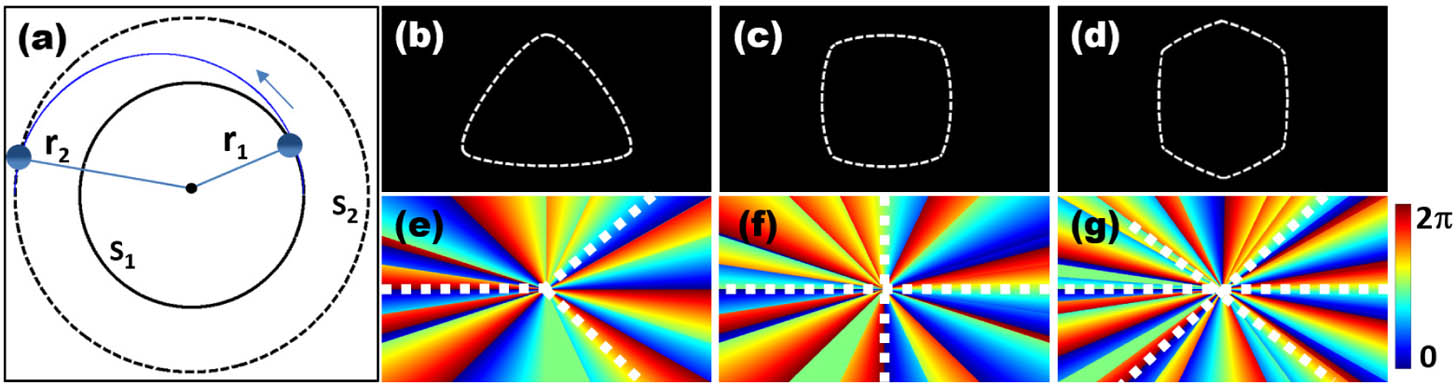
Fig. 1. (a) Schematic of trajectory change of an artificial satellite undergoing uniform circular motion. If the OAM of the artificial satellite is increased sufficiently, the artificial satellite will fly away from its original trajectory as shown by the blue curve. (b)–(d) Sketched trajectories for a “predesigned” artificial satellite motion, forming triangle, square, and hexagon patterns. (e)–(g) Desired phase distributions for generation of vortex beams with different intensity patterns corresponding to those trajectories in (b)–(d). The corner stages are marked with white dashed lines in (e)–(g).

Fig. 2. Illustration of the “cake-cutting” method of phase engineering for generation of SOV beams. (a)–(c) Phase diagrams of vortex beams of topological charge l = 6 , 7 , 8 1(b) and 1(e) .
Fig. 3. Experimental setup for the generation of SOV beams and their application in cell transportation. SLM, spatial light modulator; Lens L1 and L2, 4 f
Fig. 4. Experimental demonstrations of the SOV beams. (a)–(c) show the holograms used to generate the SOV beams. (d)–(f) show corresponding intensity patterns in triangle, square, and hexagon shapes without fine-shaping. We take the topological charges l = 6 l = 10
Fig. 5. Experimental demonstrations of the SOV beams. (a1)–(a5) show the phase distributions and (b1)–(b5) show the corresponding holograms used to generate the SOV beams; (c1)–(c5) are the corresponding intensity patterns in triangle, square, hexagon, irregular quadrilateral, and spiral-like shapes after fine-shaping with phase engineering. In (a4), the topological charge of the vortex is indicated, and in (b4), the difference in fringe numbers shows also the topological charge l = 28
Fig. 6. Demonstration of optical trapping and transporting of a yeast cell by the SOV beam. (a)–(d) are snapshots showing the motion of the trapped yeast cell along a triangular path as driven by the SOV beam (Visualization 1 ). The dashed black arrow is added to show the direction of the motion.


Set citation alerts for the article
Please enter your email address

© Copyright 2018-2021 | Chinese Laser Press. All Rights Reserved 沪ICP备15018463号-20