Abstract
We propose a method to generate specially shaped high-order singular beams of pre-designed intensity distributions. Such a method does not a priori assume a phase formula, but rather relies on the “cake-cutting and assembly” approach to achieve the azimuthal phase gradient for beam shaping, inspired by the orbital motion trajectory change of an artificial satellite. Based on our method, several typical vortex beams with desired intensity patterns are experimentally generated. As an example, we realize optical trapping and transportation of microorganisms with a triangle-shaped vortex beam, demonstrating the applicability of such unconventional vortex beams in optical trapping and manipulation.1. INTRODUCTION
Optical vortices, optical beams that carry orbital angular momentum (OAM) as proposed by Allen et al. [1], have attracted much attention due to their widespread applications in atom guiding [2], plasmonics [3,4], and information communication [5]. Such optical beams with one or more singularities are often used to transmit OAM to particles, driving them into rotation or even three-dimensional spiraling [6–15]. Specially, the helical phase of optical vortices with one singularity can be expressed by , where is the azimuthal index (topological charge) and is the azimuthal angle. In such optical vortex beams, each photon carries the OAM of , as has been used in the generation of arbitrary coherent vortex states in Bose–Einstein condensates [16]. In many of these applications, both the helical phase and the intensity distribution of the vortex beams play an essential role [7,17–22]. Over the past decade, a variety of optical vortex (OV) beams have been proposed and demonstrated, including fractional OV beams, perfect or quasi-perfect OV beams, and anomalous OV beams [23–25]. In addition, several methods have been proposed to reshape the intensity distribution of the OV beams, such as using a helical phase spatial filter [26], the power-exponent phase distribution [27,28], or the so-called phase-pitch modification [29,30]. Some of these methods are quite effective for the creation of specific vortex intensity patterns, but multiple diffractive elements are often needed, which requires complex optical setups. In addition, since multiple parameters are involved that rely on the phase equations of OV beams [27–30], shape variation in these previous settings is typically limited and cannot be easily reconfigured into other desired trajectories.
In this work, we propose and demonstrate a new method of phase engineering for the creation of various spatial intensity profiles of OV beams. Such a method contains two steps: first, inspired by the analogous change of the trajectory of an artificial satellite orbital motion, we design different intensity patterns of the vortex beam; second, we generate the corresponding phase map by “cake-cutting and assembly,” cutting off some parts of the phase diagrams of the OV beams with different topological charges and then re-combining them appropriately into a new phase diagram. Based on such a synthetic phase, we generate the desired intensity patterns of the OV beams, which we shall call synthetic optical vortex (SOV) beams. Experimentally, we demonstrate different intensity patterns of such SOV beams. Furthermore, as a typical example, we demonstrate that these specially designed OV beams can be used to trap microorganisms such as yeast cells, driving them to rotate in accordance with the designed paths.
2. DESIGN AND METHOD
Intuitively, we know that an optical vortex beam possesses OAM as does an artificial satellite that undergoes circular motion. Thus, we start with the link between the intensity pattern of a vortex beam and the trajectory change of satellite motion, and use this analog to design the change of OAM for shaping the optical vortex beam. As we know, for the family of Laguerre–Gaussian transverse modes, the radius of the donut-shaped intensity pattern of the OV beam becomes larger as the OAM of the beam increases, in a similar fashion to the trajectory of an artificial satellite having uniform circular motion. Consequently, an assumption can be made that the intensity distributions of the OV beams can be designed according to the trajectory change of an artificial satellite. Figure 1 illustrates the idea and some typical numerical results. When the OAM of the artificial satellite becomes large enough, the satellite will fly away from its original trajectory [see solid circle in Fig. 1(a)] to a new trajectory [see dashed circle in Fig. 1(a)], provided that the required centripetal potential cannot sustain its uniform circular motion. The length of semi-major axis of the Hohmann transfer orbit [31] [the transition trajectory shown as blue circle in Fig. 1(a)] can be expressed as where and are the radius of trajectory and , respectively. This process goes through two accelerations and , which can be described by [32,33] where is the standard gravitational parameter of the artificial satellite. As we see, when and in these equations change, the value of and also changes. Likewise, if the OAM of an OV beam changes, the corresponding and vary, so the density distribution of OV beam becomes more nonuniform. Thus, during the design of intensity distribution of the OV beam, the change of the OAM should go smoothly. In this way, one can construct, for example, a triangle-shaped trajectory for the artificial satellite by reconfiguring its OAM readily. In this case, the OAM of the artificial satellite is increased first and then suddenly changed back to the original value, and its trajectory will make a turn, forming one corner of the triangular pattern. Let us call this dynamic process one “corner stage”, each indicated with a white dashed line in Figs. 1(e)–1(g). If the OAM of the artificial satellite goes through three such stages, a triangular trajectory can be realized [see Fig. 1(b)]. Clearly, during these processes to form the triangle-shaped trajectory, the OAM of the artificial satellite must be in a discrete changing mode. Furthermore, one can control the number of the corners by controlling the change rate of the OAM. If the OAM of the artificial satellite goes through four and six corner stages, corresponding square- and hexagon-shaped trajectory of motion, respectively, can be realized [see Figs. 1(c) and 1(d)].
Sign up for Photonics Research TOC. Get the latest issue of Photonics Research delivered right to you!Sign up now
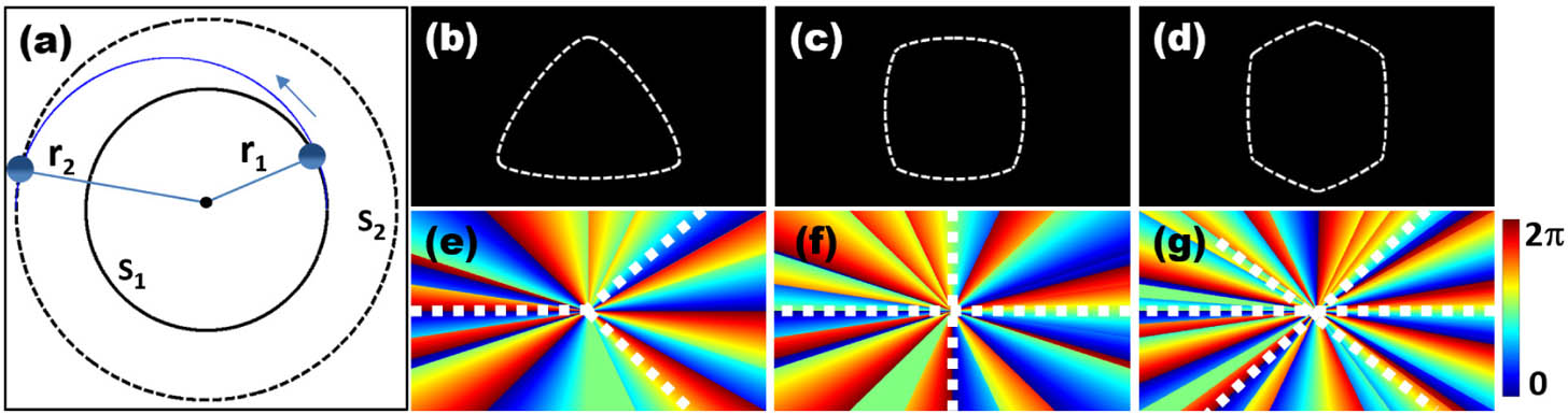
Figure 1.(a) Schematic of trajectory change of an artificial satellite undergoing uniform circular motion. If the OAM of the artificial satellite is increased sufficiently, the artificial satellite will fly away from its original trajectory as shown by the blue curve. (b)–(d) Sketched trajectories for a “predesigned” artificial satellite motion, forming triangle, square, and hexagon patterns. (e)–(g) Desired phase distributions for generation of vortex beams with different intensity patterns corresponding to those trajectories in (b)–(d). The corner stages are marked with white dashed lines in (e)–(g).
Based on this point of view, we can design OV beams with similar intensity patterns by the control of the OAM change around the azimuthal direction similar to the just-discussed artificial satellite. In order to achieve such shaped optical beams, we need to discretize the phase distribution nonuniformly from otherwise uniform OV helical phase so as to match the trajectory change shown in Figs. 1(b)–1(d). Such phase distributions corresponding to desired OAM changes are presented in Figs. 1(e)–1(g), which can lead to triangle, square, and hexagon-shaped intensity patterns as experimentally demonstrated below.
Next, let us elaborate in a bit more detail about the design of the aforementioned phase distributions [Figs. 1(e)–1(g)]. The phase function of an OV beam is in an exponential term, , where the topological charge can be an integer or a fractional number [24] and the azimuthal angle varies in the interval [0, ]. When takes a value of 6, 7, or 8, the corresponding phase maps are shown in Figs. 2(a)–2(c). During the specific operation of designing the phase distribution diagram, we use the cake-cutting method: cutting off some parts of the OV phase diagrams with different topological charges, and then splicing into a new phase diagram so as to have nonuniform OAM variations, as shown in Fig. 2. As a specific example for generating the triangular intensity pattern [Fig. 1(b)], different magnitudes of the phase gradient for the three different topological charges are used. The needed parts are digitally labeled, from (1) to (12) in Figs. 2(a)–2(c), where the boundaries are marked by the white dashed lines. In this specific operation, we cut off regions (1)–(3) from the phase map in Fig. 2(a), regions (4)–(9) in Fig. 2(b), and regions (10)–(12) in Fig. 2(c), and then assemble them into a new combined phase diagram as shown in Fig. 2(d).

Figure 2.Illustration of the “cake-cutting” method of phase engineering for generation of SOV beams. (a)–(c) Phase diagrams of vortex beams of topological charge , respectively. (d) Assembled phase diagram from slices in (a)–(c) for generation of a triangle-shaped beam as shown in Figs. 1(b) and 1(e).
Compared with the OV phase in Figs. 2(a)–2(c), the phase change in the newly combined phase diagram of Fig. 2(d) is no longer uniform. In fact, the phase diagram is composed of several parts with different phase gradients, which can be expressed by the topological charge that is increased from 6 to 8, and then decreased from 8 to 6 three times around one roundtrip azimuthally, corresponding to three corner stages in a triangular trajectory. Using such an engineered phase distribution, we can obtain a triangle-shaped beam such as that illustrated in Fig. 1(b). The otherwise donut-shaped OV beam turns into an SOV beam with discrete phase gradients around the azimuthal direction, in much the same way as the non-uniform change of the OAM which leads to the trajectory change of the motion of an artificial satellite. Note that with this design, the phase velocity is not uniform along the azimuthal direction, but rather is more rapid at the corner stages of the phase map. In a similar approach, other shapes of the SOV beams can be generated by increasing the numbers of the corner stages. As illustrated in Figs. 1(f) and 1(g), four and six corner stages in the phase diagrams can be introduced, leading to square and hexagonal intensity patterns. By using this method, we can easily generate other vortex beams with complex intensity distributions, as shown later. These vortex beams with predesigned intensity patterns are in contradistinction with commonly reported circular or broken spiral-like vortex beams [28,34].
3. EXPERIMENTAL RESULTS
To generate the proposed SOV beams experimentally, we used a setup (as sketched in Fig. 3) similar to that used for generation of morphing autofocusing Airy beams [35]. Holograms of phase information encoded onto the phase spatial light modulator (SLM) are read out by a collimated Gaussian beam (). With suitable spatial filtering through a system, the desired intensity patterns of the SOV beams can be observed. At the output, all the designed transverse intensity patterns are monitored by a CCD camera.
Figure 3.Experimental setup for the generation of SOV beams and their application in cell transportation. SLM, spatial light modulator; Lens L1 and L2, system; F, spatial filter; CCD, charge-coupled device; BS, beam splitter; O, oil immersion objective lens; Lens L3, condenser lens; WLS, white light source.
Typical experimental results for the generated SOV beams are presented in Fig. 4, where the holograms based on the previously discussed phase designs for the SLM are shown in Figs. 4(a)–4(c), and the corresponding intensity profiles of the SOV beams are shown in Figs. 4(d)–4(f). The holograms in Figs. 4(a)–4(c) are formed by a simple straight-line grating with different topological charges as composed by phase distributions in Figs. 1(e)–1(g). Figure 4(d) is supposed to be a similar triangle-shaped intensity profile because there are three corner stages, as shown in Fig. 1(e). When we change three corner stages to four or six stages, similar square or hexagon-shaped patterns are generated [Figs. 4(e) and 4(f)]. For these results, the square and hexagonal OV phase distributions are composed of three different magnitudes of the phase gradient that expressed by the topological charges , 11, 12. These results show a proof of principle that the intensity distributions of the OV beams can form similar patterns to the trajectory of artificial satellites as governed by Newton’s motion law of objects.
Figure 4.Experimental demonstrations of the SOV beams. (a)–(c) show the holograms used to generate the SOV beams. (d)–(f) show corresponding intensity patterns in triangle, square, and hexagon shapes without fine-shaping. We take the topological charges , 7, 8 in (a) and (d), and , 11, 12 in (b), (c) and (e), (f).
However, one can see clearly that the polygonal shapes in Fig. 4 are not that ideal. To reduce the intensity discontinuity of the SOV beams, we let the phase distributions vary from 0 to more continuously. In order to make the entire phase distribution vary more smoothly, each phase element is judiciously “cut” in such a way that it starts at 0 and ends at . Thus, when all phase elements are assembled into a complete phase map for the SOV beam, they do not exhibit a phase gap or discontinuity, as the phase of the whole beam varies more continuously. How “sharp” the corner is to form a good polygon vertex would depend on the topological charges of the vortex phase filaments employed, which determines how rapid the phase gradient change is at the turning point. For example, if the phase diagram of the vortex beam for the triangular pattern is assembled from , 7, 8 and then back to , 7, 6 (see Fig. 2), the low phase gradient leads to a smooth corner of triangular intensity distribution [see Fig. 4(d)]. As such, we need to increase the topological charge for all vortex phase filaments in order to synthesize a phase mask for better polygon patterns. Thus, to make a better triangle pattern, a much larger change of phase gradient (corresponding to , 30, 40 and then back to , 30, 20) is employed as shown in Figs. 5(a1), 5(b1), and 5(c1). Specifically, the phase distribution of the triangle-shaped OV [see Fig. 5(a1)] is assembled from three different vortex phase elements corresponding to the topological charges , 30, 40, whereas that for the square-shaped OV [see Fig. 5(a2)] corresponds to the topological charges , 18, 36 and that for the hexagon-shaped OV [see Fig. 5(a3)] corresponds to , 24, 36. Other variations can also be realized. By overlapping the corresponding holograms on the SLM, we generate the intensity patterns in triangle, square, hexagon, irregular quadrilateral, and special spiral shapes [Figs. 5(b1)–5(b5)]. It is worth mentioning that, as compared with Figs. 4(a)–4(c), Figs. 5(a1)–5(a3) show much finer structures of the phase modulation for the SOV beams, which leads to much smoother patterns [Figs. 5(c1)–5(c3)], indicating improved shaping of the SOV beams. The equivalent topological charges for these three cases are 30, 20, and 24, which can also be identified by careful counting of the fork bifurcations in the holograms [Figs. 5(b1)–5(b3)]. Based on the conventional phase equations [29,30], it is in principle difficult to generate irregular intensity patterns. To prove that our method has better flexibility in shaping the OV beams, we also design two complex SOV beams in the right two columns of Fig. 5, which correspond to irregular quadrilateral-shaped [Fig. 5(c4)] and spiral-shaped [Fig. 5(c5)] vortex beams. The equivalent topological charges for these two latter cases are determined to be 28 and , respectively. For the quadrilateral-shaped vortex, the charge value can be identified either by counting the multiples of the phase in one azimuthal roundtrip [Fig. 5(a4)] or by counting the fringes directly from the hologram [Fig. 5(b4)]. For the spiral-shaped vortex beams, it is hard to count precisely the fork bifurcation in the hologram [Fig. 5(b5)] since such an SOV beam involves a fractional charge. For this latter case, we counted there are 32 times of phase changes in the phase diagram [Fig. 5(a5)], plus an extra small region (1/60) cut from a separate phase map of a high-order () vortex, and thus the overall topological charge equals . These two examples prove that one can use this method to design other, more complex shapes of the OV beams. It should be noted that, as seen from the preceding results, the main issue for shaping the beam is the nonuniform change of the phase gradient along the azimuthal direction. In addition, the topological charges of the constituting vortices are also important to achieve fine-shaped patterns.
Figure 5.Experimental demonstrations of the SOV beams. (a1)–(a5) show the phase distributions and (b1)–(b5) show the corresponding holograms used to generate the SOV beams; (c1)–(c5) are the corresponding intensity patterns in triangle, square, hexagon, irregular quadrilateral, and spiral-like shapes after fine-shaping with phase engineering. In (a4), the topological charge of the vortex is indicated, and in (b4), the difference in fringe numbers shows also the topological charge . The corner stages are marked with white dashed lines in (a1)–(a3) and (a5).
Furthermore, we perform an optical tweezing experiment to show that these SOV beams can also be used in optical trapping and manipulation. For this purpose, we employ the triangle-shaped vortex beam, as an example, in the setup of optical tweezers as shown in Fig. 3. Representative experimental results are shown in Fig. 6, along with the accompanying media file. In a microscopic system, an oil immersion objective lens of a high numerical aperture (1.3) is used for focusing the triangular vortex beam into 2.5 micrometers. The beam is then used to trap and manipulate yeast cells of about 1 μm size suspended in water. The motion of yeast cells illuminated by a white-light source is recorded by a CCD camera. As seen from the snapshots of Fig. 6, under the action of the triangle-shaped vortex beam, a yeast cell moves smoothly in the direction of the dashed black arrow, whose path of motion is clearly driven to follow the triangular trajectory (see also Visualization 1).
Figure 6.Demonstration of optical trapping and transporting of a yeast cell by the SOV beam. (a)–(d) are snapshots showing the motion of the trapped yeast cell along a triangular path as driven by the SOV beam (Visualization 1). The dashed black arrow is added to show the direction of the motion.
4. CONCLUSIONS
In summary, we have proposed a method to design and generate complex intensity patterns of optical vortex beams by using an analogy to the trajectory variation of orbital motion of an artificial satellite. We have experimentally demonstrated such SOV beams and discussed how to improve the technique by judicious phase engineering for fine-shaping of the SOV beams with OAM. These SOV beams, with intensity distributions designed to the desired trajectories, may find unique applications in optical trapping and manipulation. As an example, we have demonstrated optical trapping and controlled transportation of a yeast cell along a triangular path. We envisage that these unconventionally twisted light beams may also find applications in the control of complex nanofluids [36–38] and stirred Bose–Einstein condensates, in addition to optical trapping and manipulation of cells or microparticles [39].
References
[1] L. Allen, M. W. Beijersbergen, R. J. C. Spreeuw, J. P. Woerdman. Orbital angular momentum of light and the transformation of Laguerre-Gaussian laser modes. Phys. Rev. A, 45, 8185-8189(1992).
[2] J. Arlt, T. Hitomi, K. Dholakia. Atom guiding along Laguerre-Gaussian and Bessel light beams. Appl. Phys. B, 71, 549-554(2000).
[3] N. Shitrit, I. Bretner, Y. Gorodetski, V. Kleiner, E. Hasman. Optical spin Hall effects in plasmonic chains. Nano Lett., 11, 2038-2042(2011).
[4] H. Kim, J. Park, S.-W. Cho, S.-Y. Lee, M. Kang, B. Lee. Synthesis and dynamic switching of surface plasmon vortices with plasmonic vortex lens. Nano Lett., 10, 529-536(2010).
[5] J. Wang. Advances in communications using optical vortices. Photon. Res., 4, B14-B28(2016).
[6] J. Zhao, I. D. Chremmos, D. Song, D. N. Christodoulides, N. K. Efremidis, Z. Chen. Curved singular beams for three-dimensional particle manipulation. Sci. Rep., 5, 12086(2015).
[7] A. Lehmuskero, P. Johansson, H. Rubinsztein-Dunlop, L. Tong, M. Kall. Laser trapping of colloidal metal nanoparticles. ACS Nano, 9, 3453-3469(2015).
[8] P. Zhang, D. Hernandez, D. Cannan, Y. Hu, S. Fardad, S. Huang, J. C. Chen, D. N. Christodoulides, Z. Chen. Trapping and rotating microparticles and bacteria with Moire-based optical propelling beams. Biomed. Opt. Express, 3, 1891-1897(2012).
[9] M. Padgett, R. Bowman. Tweezers with a twist. Nat. Photonics, 5, 343-348(2011).
[10] M. Z. Chen, M. Mazilu, Y. Arita, E. M. Wright, K. Dholakia. Creating and probing of a perfect vortex in situ with an optically trapped particle. Opt. Rev., 22, 162-165(2015).
[11] Y. Roichman, B. Sun, Y. Roichman, J. Amato-Grill, D. G. Grier. Optical forces arising from phase gradients. Phys. Rev. Lett., 100, 013602(2008).
[12] C. P. Lapointe, T. G. Mason, I. I. Smalyukh. Towards total photonic control of complex-shaped colloids by vortex beams. Opt. Express, 19, 18182-18189(2011).
[13] Y. J. Shen, Z. S. Wan, Y. Meng, X. Fu, M. L. Gong. Polygonal vortex beams. IEEE Photon. J., 10, 1503016(2018).
[14] E. G. Abramochkin, V. G. Volostnikov. Spiral light beams. Phys. Usp., 47, 1177-1203(2004).
[15] E. G. Abramochkin, K. N. Afanasiev, V. G. Volostnikov, A. V. Korobtsov, S. P. Kotova, N. N. Losevsky, A. M. Mayorova, E. V. Razueva. Formation of vortex light fields of specified intensity for laser micromanipulation. Biol. Bull. Russ. Acad. Sci. Phys., 72, 68-70(2008).
[16] K. T. Kapale, J. P. Dowling. Vortex phase qubit: generating arbitrary, counterrotating, coherent superpositions in Bose-Einstein condensates via optical angular momentum beams. Phys. Rev. Lett., 95, 173601(2005).
[17] J. Lin, X. C. Yuan, S. H. Tao, X. Peng, H. B. Niu. Deterministic approach to the generation of modified helical beams for optical manipulation. Opt. Express, 13, 3862-3867(2005).
[18] M. Daly, M. Sergides, S. N. Chormaic. Optical trapping and manipulation of micrometer and submicrometer particles. Laser Photon. Rev., 9, 309-329(2015).
[19] D. G. Grier. A revolution in optical manipulation. Nature, 424, 810-816(2003).
[20] K. Dholakia, T. Cizmar. Shaping the future of manipulation. Nat. Photonics, 5, 335-342(2011).
[21] M. Chen, M. Mazilu, Y. Arita, E. M. Wright, K. Dholakia. Dynamics of microparticles trapped in a perfect vortex beam. Opt. Lett., 38, 4919-4922(2013).
[22] Y. Liang, M. Lei, S. Yan, M. Li, Y. Cai, Z. Wang, X. Yu, B. Yao. Rotating of low-refractive-index microparticles with a quasi-perfect optical vortex. Appl. Opt., 57, 79-84(2018).
[23] Y. Yang, X. Zhu, J. Zeng, X. Lu, C. Zhao, Y. Cai. Anomalous Bessel vortex beam: modulating orbital angular momentum with propagation. Nanophotonics, 7, 677-682(2018).
[24] S. H. Tao, X. C. Yuan, J. Lin, X. Peng, H. B. Niu. Fractional optical vortex beam induced rotation of particles. Opt. Express, 13, 7726-7731(2005).
[25] M. Gecevicius, R. Drevinskas, M. Beresna, P. G. Kazansky. Single beam optical vortex tweezers with tunable orbital angular momentum. Appl. Phys. Lett., 104, 231110(2014).
[26] C. S. Guo, Y. Zhang, Y. J. Han, J. P. Ding, H. T. Wang. Generation of optical vortices with arbitrary shape and array via helical phase spatial filtering. Opt. Commun., 259, 449-454(2006).
[27] G. Lao, Z. Zhang, D. Zhao. Propagation of the power-exponent-phase vortex beam in paraxial ABCD system. Opt. Express, 24, 18082-18094(2016).
[28] P. Li, S. Liu, T. Peng, G. Xie, X. Gan, J. Zhao. Spiral autofocusing Airy beams carrying power-exponent-phase vortices. Opt. Express, 22, 7598-7606(2014).
[29] J. E. Curtis, D. G. Grier. Modulated optical vortices. Opt. Lett., 28, 872-874(2003).
[30] L. Yang, D. Qian, C. Xin, Z. Hu, S. Ji, D. Wu, Y. Hu, J. Li, W. Huang, J. Chu. Direct laser writing of complex microtubes using femtosecond vortex beams. Appl. Phys. Lett., 110, 221103(2017).
[31] S. T. Thornton, J. B. Marion. Classical Dynamics of Particles and Systems(2003).
[32] R. R. Bate, D. D. Mueller, J. E. White. Fundamentals of Astrodynamics(1971).
[33] R. H. Battin. An Introduction to the Mathematics and Methods of Astrodynamics(1999).
[34] Y. Yang, Y. Dong, C. Zhao, Y. Cai. Generation and propagation of an anomalous vortex beam. Opt. Lett., 38, 5418-5421(2013).
[35] P. Zhang, J. Prakash, Z. Zhang, M. S. Mills, N. K. Efremidis, D. N. Christodoulides, Z. Chen. Trapping and guiding microparticles with morphing autofocusing Airy beams. Opt. Lett., 36, 2883-2885(2011).
[36] Y. Lamhot, A. Barak, C. Rotschild, M. Segev, M. Saraf, E. Lifshitz, A. Marmur, R. El-Ganainy, D. N. Christodoulides. Optical control of thermocapillary effects in complex nanofluids. Phys. Rev. Lett., 103, 264503(2009).
[37] M. Krishnan, N. Mojarad, P. Kukura, V. Sandoghdar. Geometry-induced electrostatic trapping of nanometric objects in a fluid. Nature, 467, 692-695(2010).
[38] A. Terray, J. Oakey, D. W. M. Marr. Microfluidic control using colloidal devices. Science, 296, 1841-1844(2002).
[39] A. Balijepalli, J. J. Gorman, S. K. Gupta, T. W. LeBrun. Significantly improved trapping lifetime of nanoparticles in an optical trap using feedback control. Nano Lett., 12, 2347-2351(2012).


