• Matter and Radiation at Extremes
  • Vol. 6, Issue 1, 015401 (2021)
N. Jourdain1, U. Chaulagain1, M. Havlík1, D. Kramer1, D. Kumar1, I. Majerová1, V. T. Tikhonchuk1、2, G. Korn1, and S. Weber1、3、a)
Author Affiliations
  • 1ELI-Beamlines, Institute of Physics, Czech Academy of Sciences, 18221 Prague, Czech Republic
  • 2Centre Lasers Intenses et Applications, University of Bordeaux–CNRS–CEA, 33405 Talence, France
  • 3School of Science, Xi’an Jiaotong University, Xi’an 710049, China
  • show less
    DOI: 10.1063/5.0022120 Cite this Article
    N. Jourdain, U. Chaulagain, M. Havlík, D. Kramer, D. Kumar, I. Majerová, V. T. Tikhonchuk, G. Korn, S. Weber. The L4n laser beamline of the P3-installation: Towards high-repetition rate high-energy density physics at ELI-Beamlines[J]. Matter and Radiation at Extremes, 2021, 6(1): 015401 Copy Citation Text show less
    The E3 experimental hall for plasma physics and beam configurations. The L4n pulse (1.9 kJ, 0.5 ns–10 ns, 1053 nm) is shown in pink. Three other beams will also be available in E3: L4f (1.5 kJ, 150 fs, 1053 nm), L4p (available in 2022) (150 J–400 J, 150 fs to 150 ps, 1053 nm), and L3 (30 J, 30 fs, 800 nm, 10 Hz).
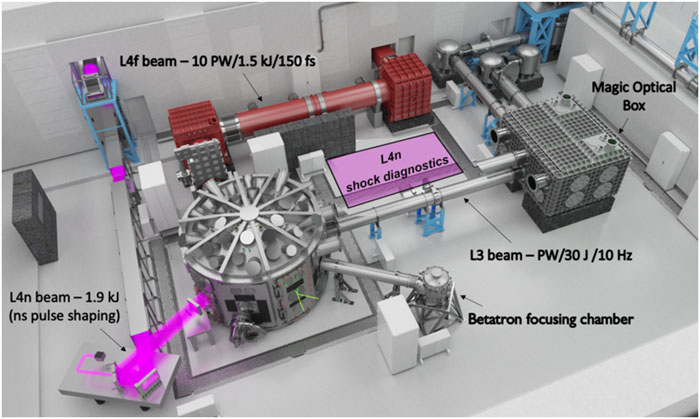
    Fig. 1. The E3 experimental hall for plasma physics and beam configurations. The L4n pulse (1.9 kJ, 0.5 ns–10 ns, 1053 nm) is shown in pink. Three other beams will also be available in E3: L4f (1.5 kJ, 150 fs, 1053 nm), L4p (available in 2022) (150 J–400 J, 150 fs to 150 ps, 1053 nm), and L3 (30 J, 30 fs, 800 nm, 10 Hz).
    Schematic of the L4 ATON laser in the high-power non-CPA configuration.
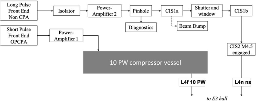
    Fig. 2. Schematic of the L4 ATON laser in the high-power non-CPA configuration.
    Layout of the compressor imaging system (CIS) with its optical scheme in the chirped pulse beamline (a) and with the M4.5 mirror position defined from Zemax OpticStudio simulations (b).
    Fig. 3. Layout of the compressor imaging system (CIS) with its optical scheme in the chirped pulse beamline (a) and with the M4.5 mirror position defined from Zemax OpticStudio simulations (b).
    (a) Design of the L4n beamline in the E3 experimental hall. The L4n beam is shown in pink up to the frequency-doubling KDP crystal. The converted 2ω beam is then shown in green. (b) Optical layout extracted from Zemax OpticStudio simulations.
    Fig. 4. (a) Design of the L4n beamline in the E3 experimental hall. The L4n beam is shown in pink up to the frequency-doubling KDP crystal. The converted 2ω beam is then shown in green. (b) Optical layout extracted from Zemax OpticStudio simulations.
    (a) Diffraction-limited focal spot with 0.2° lens tilt and 1 W input power in a square beam. (b) Focal spot with 0.42° lens tilt and 1 W input power in a square beam.
    Fig. 5. (a) Diffraction-limited focal spot with 0.2° lens tilt and 1 W input power in a square beam. (b) Focal spot with 0.42° lens tilt and 1 W input power in a square beam.
    Calculated KDP crystal conversion efficiency to second harmonic with 1 kJ as energy input.
    Fig. 6. Calculated KDP crystal conversion efficiency to second harmonic with 1 kJ as energy input.
    (a) Focal spot intensity profile (arbitrary units) simulated using wave front data from one of the phase plates. (b) Horizontal slice of the intensity profile.
    Fig. 7. (a) Focal spot intensity profile (arbitrary units) simulated using wave front data from one of the phase plates. (b) Horizontal slice of the intensity profile.
    The left panels show laser pulse temporal profiles providing access to the Hugoniot adiabat and far-from-Hugoniot states. The right panels show the corresponding trajectories in the phase plane P–ρ. (a) Steady and quasi-isentropic compression. (b) Decaying shock and ramp compression. (c) Double shock. Adapted from Refs. 39,40.
    Fig. 8. The left panels show laser pulse temporal profiles providing access to the Hugoniot adiabat and far-from-Hugoniot states. The right panels show the corresponding trajectories in the phase plane Pρ. (a) Steady and quasi-isentropic compression. (b) Decaying shock and ramp compression. (c) Double shock. Adapted from Refs. 39,40.
    Configurations for multibeam experiments with L4n (green) and L3 (yellow) pulses: (a) long-focal-length (5 m) configuration in which L3 is focused in a gas jet and generates relativistic electrons and broadband hard X-rays at an angle of 112° with respect to the L4n beam; (b) short-focal-length (f = 750 mm) configuration in which the L3 pulse is focused by an off-axis parabola (OAP) at an angle of 58° with respect to the L4n beam.
    Fig. 9. Configurations for multibeam experiments with L4n (green) and L3 (yellow) pulses: (a) long-focal-length (5 m) configuration in which L3 is focused in a gas jet and generates relativistic electrons and broadband hard X-rays at an angle of 112° with respect to the L4n beam; (b) short-focal-length (f = 750 mm) configuration in which the L3 pulse is focused by an off-axis parabola (OAP) at an angle of 58° with respect to the L4n beam.
    InstallationOperating facilityλ (nm)Maximum energy (long pulse)Repetition rate
    NIFLLNL (Livermore, USA)10532.1 MJ (3ω, 3 ns–15 ns)Every 8 h
    LMJCEA (Le Barp, France)10531.4 MJ (3ω, 3 ns–15 ns)Every 8 h
    Omega EPLLE (Rochester, USA)105330 kJ (3ω, 1 ns–3 ns)Every 90 min
    SG-II-UPSIOM (Shanghai, China)105324 kJ (3ω, 3 ns)Every 3 h
    Gekko XIIILE (Osaka, Japan)106410 kJ (2ω, 1 ns)Every 30 min
    OrionAWE (Aldermaston, UK)10535 kJ (3ω, 1 ns)Every 45 min
    L4nELI-Beamlines (Prague, Czech Republic)10531.2 kJ (2ω, 1 ns–5 ns)1 shot/min
    VULCANCLF, STFC (Oxford, UK)10531 kJ (2ω, 1 ns–10 ns)2 shots/day
    PALSIoP (Prague, Czech Republic)1315200 J (3ω, 250 ps)Every 25 min
    LULI 2000LULI, CEA (Paris, France)1053750 J (2ω, 1.5 ns)Every 90 min
    MECSLAC (Menlo Park, USA)105360 J (2ω, 10 ns)Every 7 min
    HIBEFEu-XFEL (Schenefeld, Germany)1053100 J (1ω, 10 ns)10 Hz
    Table 1. Overview of the current performance of major high-energy laser facilities in a long-pulse configuration listing the name of the installation, the operating entity, the laser wavelength in nanometers, the maximum energy available per shot, and the operating repetition rate.7
    Beam dimensions32 × 32 cm2
    Central wavelengthλ = 1053.2 nm
    Energy1.9 kJ
    Pulse durationτ = 0.1 ns–10 ns
    Strehl ratio∼0.5
    Pointing stability<10 µrad
    Beam shapeSquare super-Gaussian (order ∼20)
    Table 2. L4n laser specifications.
    RequirementSpecification
    Maximum energy 1ω1.9 kJ
    Maximum energy 2ω1 kJ
    Beam dimensions initial phase25 cm diameter
    Maximum energy 1ω subaperture beam1 kJ
    Conversion efficiencyBest effort >60%
    Best spot diameter50 µm
    Spot diameter after conditioning>300 µm
    Nominal focus position±2 mm lateral/±5 mm longitudinal
    Synchronization20 ps
    Pointing stability<5 µrad on KDP crystal
    Maximum repetition rate at 2ω1 shot/min
    Table 3. Requirements on the nominal L4n design.
    Clear aperture284 ± 1 mm
    Phase matching angle59 ± 0.2°
    Damage threshold>10 J/cm2 at 1 ns
    Table 4. Main specifications of frequency-doubling KDP crystal.
    N. Jourdain, U. Chaulagain, M. Havlík, D. Kramer, D. Kumar, I. Majerová, V. T. Tikhonchuk, G. Korn, S. Weber. The L4n laser beamline of the P3-installation: Towards high-repetition rate high-energy density physics at ELI-Beamlines[J]. Matter and Radiation at Extremes, 2021, 6(1): 015401
    Download Citation