
N. Jourdain, U. Chaulagain, M. Havlík, D. Kramer, D. Kumar, I. Majerová, V. T. Tikhonchuk, G. Korn, S. Weber. The L4n laser beamline of the P3-installation: Towards high-repetition rate high-energy density physics at ELI-Beamlines[J]. Matter and Radiation at Extremes, 2021, 6(1): 015401
- Matter and Radiation at Extremes
- Vol. 6, Issue 1, 015401 (2021)
Abstract
I. INTRODUCTION
ELI-Beamlines is a part of the Extreme Light Infrastructure (ELI) project and will soon become one of the most powerful laser facilities in the world.
![]()
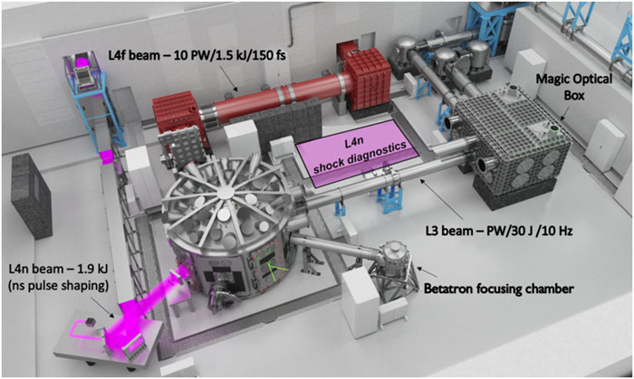
Figure 1.The E3 experimental hall for plasma physics and beam configurations. The L4n pulse (1.9 kJ, 0.5 ns–10 ns, 1053 nm) is shown in pink. Three other beams will also be available in E3: L4f (1.5 kJ, 150 fs, 1053 nm), L4p (available in 2022) (150 J–400 J, 150 fs to 150 ps, 1053 nm), and L3 (30 J, 30 fs, 800 nm, 10 Hz).
Of particular interest for the physics of matter in extreme states is the nanosecond high-energy L4n beam shown in pink in
| Installation | Operating facility | λ (nm) | Maximum energy (long pulse) | Repetition rate |
|---|---|---|---|---|
| NIF | LLNL (Livermore, USA) | 1053 | 2.1 MJ (3ω, 3 ns–15 ns) | Every 8 h |
| LMJ | CEA (Le Barp, France) | 1053 | 1.4 MJ (3ω, 3 ns–15 ns) | Every 8 h |
| Omega EP | LLE (Rochester, USA) | 1053 | 30 kJ (3ω, 1 ns–3 ns) | Every 90 min |
| SG-II-UP | SIOM (Shanghai, China) | 1053 | 24 kJ (3ω, 3 ns) | Every 3 h |
| Gekko XII | ILE (Osaka, Japan) | 1064 | 10 kJ (2ω, 1 ns) | Every 30 min |
| Orion | AWE (Aldermaston, UK) | 1053 | 5 kJ (3ω, 1 ns) | Every 45 min |
| VULCAN | CLF, STFC (Oxford, UK) | 1053 | 1 kJ (2ω, 1 ns–10 ns) | 2 shots/day |
| PALS | IoP (Prague, Czech Republic) | 1315 | 200 J (3ω, 250 ps) | Every 25 min |
| LULI 2000 | LULI, CEA (Paris, France) | 1053 | 750 J (2ω, 1.5 ns) | Every 90 min |
| MEC | SLAC (Menlo Park, USA) | 1053 | 60 J (2ω, 10 ns) | Every 7 min |
| HIBEF | Eu-XFEL (Schenefeld, Germany) | 1053 | 100 J (1ω, 10 ns) | 10 Hz |
Table 1. Overview of the current performance of major high-energy laser facilities in a long-pulse configuration listing the name of the installation, the operating entity, the laser wavelength in nanometers, the maximum energy available per shot, and the operating repetition rate.
An increase in the shot number capacity will have a significant impact on fields related to inertial confinement fusion
Interpretations of data in high-energy-density physics experiments are not always straightforward and can lead to inconsistency among different studies. This applies in particular to dynamic compression experiments, which are affected by a shortage of statistics and large error bars. Major discrepancies were found in SiO2 equation-of-state (EoS) measurements, which had a consequent impact on the determination of the deuterium EoS.
Two solutions have been envisaged to overcome this lack of statistics: either through obtaining more precise data by improving the measurement techniques and diagnostics or by significantly increasing the number of shots. While recent studies have proved that it is possible to acquire shock velocity measurements with uncertainties lower than 1%,
The remainder of the paper is structured as follows. Section
II. THE L4n BEAMLINE
A. L4 laser
The L4 laser will provide 10-PW-class peak power pulses, with nominal energy of 1.5 kJ and duration 150 fs. It is being developed by a consortium of the National Energetics/EKSPLA and ELI-Beamlines. An exhaustive description of the L4 laser is presented in Refs.
![]()
Figure 2.Schematic of the L4 ATON laser in the high-power non-CPA configuration.
The compressor imaging system (CIS) is located in the hall adjacent to the E3 hall. Its final purpose is to transport the chirped beam from the laser to the compressor as well as the nonchirped beam to the L4n beamline on demand. The L4n pulse has to be diverted from the CIS path with a slide-in mirror. This is indicated as M4.5 in
![]()
Figure 3.Layout of the compressor imaging system (CIS) with its optical scheme in the chirped pulse beamline (a) and with the M4.5 mirror position defined from Zemax OpticStudio simulations (b).
B. L4n beam properties
The main L4n pulse specifications are presented in
| Beam dimensions | 32 × 32 cm2 |
| Central wavelength | λ = 1053.2 nm |
| Energy | 1.9 kJ |
| Pulse duration | τ = 0.1 ns–10 ns |
| Strehl ratio | ∼0.5 |
| Pointing stability | <10 µrad |
| Beam shape | Square super-Gaussian (order ∼20) |
Table 2. L4n laser specifications.
In addition, several conditions are required on the laser to enable the performance of high-energy-density physics experiments in a repetitive regime: the laser driver energy has to be reliable on a shot-to-shot basis, the intensity distribution over the focal spot should be as uniform as possible, and a very precise and reproducible pulse temporal profile is needed to control the pressure in the sample.
C. Layout of beams in the E3 experimental hall
L4n experiments will be carried out in the E3 hall. The beamline design in this area is shown in
![]()
Figure 4.(a) Design of the L4n beamline in the E3 experimental hall. The L4n beam is shown in pink up to the frequency-doubling KDP crystal. The converted 2
The L4n beam is then spatially smoothed with a phase plate. Currently, two distributed phase plates (DPPs) designed for focal spots with full width at half maximum (FWHM) of 500 μm and 700 µm are available. Initially, L4n will operate with a subaperture circular beam of 25 cm diameter imposed by the dimensions of the first set of KDP crystal and DPP available. The aspherical focusing lens with a back focal length of 2600 mm is located outside the P3 interaction chamber owing to concerns about debris. Particular attention is paid to ghost reflections, and the optical design has been realized accordingly. More details are provided in Sec.
| Requirement | Specification |
|---|---|
| Maximum energy 1ω | 1.9 kJ |
| Maximum energy 2ω | 1 kJ |
| Beam dimensions initial phase | 25 cm diameter |
| Maximum energy 1ω subaperture beam | 1 kJ |
| Conversion efficiency | Best effort >60% |
| Best spot diameter | 50 µm |
| Spot diameter after conditioning | >300 µm |
| Nominal focus position | ±2 mm lateral/±5 mm longitudinal |
| Synchronization | 20 ps |
| Pointing stability | <5 µrad on KDP crystal |
| Maximum repetition rate at 2ω | 1 shot/min |
Table 3. Requirements on the nominal L4n design.
D. Description of main L4n beamline optics
The beamline will be initially equipped with a subaperture round 300 mm KDP crystal, thus limiting the first-harmonic energy to 1 kJ. The remaining optical elements are being procured for the final square beam size as specified in
The design process resulted in a meniscus lens with one aspherical side and a back focal length of 2600 mm. Only the conical constant was used for the departure from sphericity. The nominal focal spot diameter will be diffraction-limited if the phase plate is removed from the beamline, as shown in the OpticStudio simulation in
![]()
Figure 5.(a) Diffraction-limited focal spot with 0.2° lens tilt and 1 W input power in a square beam. (b) Focal spot with 0.42° lens tilt and 1 W input power in a square beam.
The L4n pulse will be frequency-doubled with a KDP crystal whose main specifications are listed in
| Clear aperture | 284 ± 1 mm |
| Phase matching angle | 59 ± 0.2° |
| Damage threshold | >10 J/cm2 at 1 ns |
Table 4. Main specifications of frequency-doubling KDP crystal.
![]()
Figure 6.Calculated KDP crystal conversion efficiency to second harmonic with 1 kJ as energy input.
To achieve a uniform spatial pulse shape in the focal plane, two phase plates have been procured. These plates have continuously varying random phase profiles and are sol–gel AR-coated. The spot profile from a ray tracing simulation using the measured wave front data of the first wave plate is shown in
![]()
Figure 7.(a) Focal spot intensity profile (arbitrary units) simulated using wave front data from one of the phase plates. (b) Horizontal slice of the intensity profile.
E. Repetition rate capacity
The repetition rate for the first experiment will be about one shot every 10 min. This rate is chosen as a compromise based on analysis of machine safety, the cooling rate of the conversion KDP crystal, and the wave front stability of the laser. Active cooling of the KDP crystal will be necessary in order to reach a higher repetition rate, since, according to our calculations, the conversion efficiency drops rapidly to 50% after several shots without cooling.
The actively cooled KDP system design is ongoing in parallel to the L4n beamline design and will be implemented soon after the initial experiments.
F. Beam diagnostics
The main laser diagnostics package will be located behind the second dichroic mirror. A spare lens from the main beamline will focus the leakage beam. The demagnified beam will be imaged to near-field diagnostics at the main wavelength and the second harmonic and far field at 2ω. The energy will be monitored for both harmonics as well. The temporal pulse shape will be monitored by a high-bandwidth (11 GHz) transient digitizer with a high-precision timing reference. The amount of backreflection to the laser will be monitored for machine protection only if the KDP is not to be used.
G. Challenges with operation in a repetitive regime
High-energy lasers running at a considerable repetition rate face many challenges. The following are the main issues that have been foreseen.
First, the laser pulse quality needs to be good enough, with small shot-to-shot fluctuations. This means that the intensity distribution in the focal spot should be very stable and the temporal profile as robust as possible. This is crucial to increase the accuracy of the statistics in the datasets. Another major concern is related to targets. Mass production of targets is required, since hundreds of them will be shot per day.
Appropriate vacuum conditions (∼10−5 mbar) have to be maintained in the chamber throughout the shot sequences. Given the volume of the P3 interaction chamber (∼50 m3) and the substantial pumping system, this can be achieved without major difficulty. A big challenge is the need to collect and analyze large datasets. This requires high storage capability and the capability to perform on-line data analysis for rapid interventions during shots, if needed. Detectors also have to be compatible with multiple successive acquisitions while being remotely controlled. For example, image plates will no longer be appropriate for X-ray diagnostics, since they must be replaced after each shot, while the chamber cannot be vented between shots. Finally, protection from electromagnetic pulses (EMPs) must be ensured.
III. PERSPECTIVES FOR FUTURE EXPERIMENTS
A. Pulse shaping to reach far-from-Hugoniot states
The use of steady shocks restricts studies to states along the Rankine–Hugoniot adiabat. To access states far from the Hugoniot, precise temporal shaping of the pulse is necessary. Various shock loading techniques like those described in Ref.
![]()
Figure 8.The left panels show laser pulse temporal profiles providing access to the Hugoniot adiabat and far-from-Hugoniot states. The right panels show the corresponding trajectories in the phase plane
In addition, more sophisticated pulse shaping techniques can be used in dynamic compression experiments. This includes quasi-isentropic compression [
B. Demonstrating the benefit of the increase of statistics in EoS measurements
One of the major contributions of the L4n beamline to the scientific community will be an improvement in data interpretation by decreasing the statistical errors in experiments performed with kilojoule-class lasers. Such progress will be demonstrated under the experimental conditions that have allowed ambiguous interpretations in several works over the past years.
The element chosen for this study is magnesium oxide (MgO), which is of great importance for planetary science since it is a major component of the deep mantles of terrestrial planets and exoplanets. Despite numerous studies in recent years, the MgO phase diagram and the phase transition boundary conditions in the pressure–temperature (P–T) diagram at high pressure (up to ∼7 Mbar) are still uncertain.
The experimental data will be compared with theoretical models reported in Refs.
C. Multibeam experiments
In future experiments, the high-energy L4n pulse will be coupled with petawatt pulses produced by the L3 laser.
![]()
Figure 9.Configurations for multibeam experiments with L4n (green) and L3 (yellow) pulses: (a) long-focal-length (5 m) configuration in which L3 is focused in a gas jet and generates relativistic electrons and broadband hard X-rays at an angle of 112° with respect to the L4n beam; (b) short-focal-length (
In the long-focal-length configuration, L3 is focused over 5 m by an f/20 spherical mirror in a gas jet and drives a relativistic electron beam via laser wakefield acceleration (LWFA). The complete experimental layout of this betatron setup on the P3 platform is described in Ref.
In the short-focal-length configuration, the L3 pulse will be directly focused on the target with an f/3 off-axis parabola (OAP). This offers the possibility of generating hard X-rays
Time-resolved pump–probe experiments can be performed in warm dense matter, with the L4n pulse acting as a pump beam. The broadband betatron X-ray beam will be used to perform time-resolved X-ray absorption studies.
Bright and broadband betatron X-ray emission is an ideal source providing a real-time, nonintrusive diagnosis of material behavior at the micro- and mesoscales.
A nanosecond kilojoule L4n laser pulse can drive a hypersonic radiative shock wave in a gas target, which is relevant to astrophysical objects.
IV. CONCLUSIONS AND PERSPECTIVES
The L4n laser at ELI-Beamlines offers users a platform for high-energy-density physics experiments at a high repetition rate. This is of great interest in this field, where the available data suffer from poor statistics. The first, short-term, objective is commissioning of the L4n beamline and shock diagnostics in a dynamic compression experiment. Implementation of active cooling of the KDP conversion crystal will then allow the repetition rate to be increased to an unprecedented level of 1 shot/min. This platform for high-energy-density physics will subsequently be developed with complementary tools, including hard X-ray and high-energy charged particle diagnostics, which can provide key information about the structural evolution of materials under extreme pressures and temperatures.
References
[1] G. Mourou, G. Korn, W. Sandner, J. Collier. ELI Extreme Light Infrastructure (Whitebook)(2011).
[3] S. V. Bulanov, G. A. Mourou, T. Tajima. Optics in the relativistic regime. Rev. Mod. Phys., 78, 309(2006).
[4] R. P. Drake. High-Energy-Density Physics: Fundamentals, Inertial Fusion, and Experimental Astrophysics(2006).
[5] F. Graziani, M. Desjarlais, R. Redmer, S. Trickey. Frontiers and Challenges in Warm Dense Matter(2014).
[6] J.-P. Geindre, F. Quéré, C. Thaury et al. Plasma mirrors for ultrahigh-intensity optics. Nat. Phys., 3, 424(2007).
[7] S. Bechet, S. Borneis, S. Weber et al. P3: An installation for high-energy density plasma physics and ultra-high intensity laser–matter interaction at ELI-Beamlines. Matter Radiat. Extremes, 2, 149(2017).
[8] R. N. Boyd, E. I. Moses, B. A. Remington et al. The national ignition facility: Ushering in a new age for high energy density science. Phys. Plasmas, 16, 041006(2009).
[9] C. Lion, J.-L. Miquel, P. Vivini. The laser mega-joule: LMJ & PETAL status and program overview. J. Phys.: Conf. Ser., 688, 012067(2016).
[10] V. Bagnoud, J. Kelly, L. Waxer et al. OMEGA EP: High-energy petawatt capability for the OMEGA laser facility. J. Phys., 133, 75-80(2005).
[11] Y. Gao, W.-x. Ma, B.-Q. Zhu et al. Status of the SG-II-UP laser facility, 73-74(2013).
[12] C. Danson, S. Duffield, N. Hopps et al. Overview of laser systems for the Orion facility at the AWE. Appl. Opt., 52, 3597-3607(2013).
[13] P. Brummitt, R. Clarke, C. Danson et al. Vulcan Petawatt—An ultra-high-intensity interaction facility. Nucl. Fusion, 44, S239(2004).
[14] A. Cejnarova, L. Juha, K. Jungwirth et al. The Prague asterix laser system. Phys. Plasmas, 8, 2495-2501(2001).
[15] A. Benuzzi-Mounaix, M. Koenig, N. Ozaki et al. High energy density physics on LULI2000 laser facility. AIP Conf. Proc., 845, 1421-1424(2006).
[16] S. B. Brown, A. Gleason, A. Hashim et al. Shock drive capabilities of a 30-Joule laser at the matter in extreme conditions hutch of the linac coherent light source. Rev. Sci. Instrum., 88, 105113(2017).
[17] D. Callahan, D. T. Casey, O. Hurricane et al. Inertially confined fusion plasmas dominated by alpha-particle self-heating. Nat. Phys., 12, 800(2016).
[18] L. F. Berzak Hopkins, L. Divol, S. Le Pape et al. Fusion energy output greater than the kinetic energy of an imploding shell at the National Ignition Facility. Phys. Rev. Lett., 120, 245003(2018).
[19] J.-L. Miquel, E. Prene. LMJ and PETAL status and program overview. Nucl. Fusion, 59, 032005(2019).
[20] S. Fujioka, N. Yamamoto, Z. Zhang et al. High-energy-density plasmas generation on GEKKO-LFEX laser facility for fast-ignition laser fusion studies and laboratory astrophysics. Plasma Phys. Controlled Fusion, 54, 124042(2012).
[21] C. Danson, A. Randewich. High energy density physics at the atomic weapons establishment. High Power Laser Sci. Eng., 2, e40(2014).
[22] D. Kraus, A. Pak, J. Vorberger et al. Formation of diamonds in laser-compressed hydrocarbons at planetary interior conditions. Nat. Astron., 1, 606(2017).
[23] S. Banerjee, P. Mason, J. Smith et al. Development of a 100 J, 10 Hz laser for compression experiments at the high energy density instrument at the European XFEL. High Power Laser Sci. Eng., 6, e65(2018).
[24] R. Betti, O. A. Hurricane. Inertial-confinement fusion with lasers. Nat. Phys., 12, 435(2016).
[25] B. A. Remington. High energy density laboratory astrophysics. Plasma Phys. Controlled Fusion, 47, A191(2005).
[26] M. P. Desjarlais, M. D. Knudson. Shock compression of quartz to 1.6 TPa: Redefining a pressure standard. Phys. Rev. Lett., 103, 225501(2009).
[27] C. E. Ragan. Ultrahigh-pressure shock-wave experiments. Phys. Rev. A, 21, 458(1980).
[28] A. Fernandez-Pañella, D. E. Fratanduono, M. Millot et al. Shock compression of liquid deuterium up to 1 TPa. Phys. Rev. Lett., 122, 255702(2019).
[29] P. Bakule, D. Kramer, B. Rus et al. ELI-Beamlines: Development of next generation short-pulse laser systems. Proc. SPIE., 9515, 95150F(2015).
[30] R. Antipenkov, J. Bartonicek, F. Batysta et al. Spectral shaping of a 5 Hz, multi-joule OPCPA frontend for a 10 PW laser system. Proc. SPIE., 11034, 11034OC(2019).
[31] M. Kepler, D. Kramer, S. Vyhlidka et al. Optimization of a grating pulse stretcher suitable for kJ class 10 PW laser system. Proc. SPIE., 10238, 102380T(2017).
[32] R. Antipenkov, G. Cheriaux, E. Gaul et al. kJ-10 PW class laser system at 1 shot a minute. SPIE Proc., 10898, 1089806(2019).
[33] R. Antipenkov, G. Cheriaux, E. Gaul et al. Hybrid OPCPA/glass 10 PW laser at 1 shot a minute(2018).
[34] O. Morice. Miro: Complete modeling and software for pulse amplification and propagation in high-power laser systems. Opt. Eng., 42, 1530-1541(2003).
[35] J. Fuchs, S. Pascarelli, I. Prencipe et al. Targets for high repetition rate laser facilities: Needs, challenges and perspectives. High Power Laser Sci. Eng., 5, e17(2017).
[36] G. H. Dahlbacka, J. S. Pearlman. Emission of rf radiation from laser-produced plasmas. J. Appl. Phys., 49, 457(1978).
[37] M. Bailly-Grandvaux, S. Hulin, A. Poyé et al. Physics of giant electromagnetic pulse generation in short-pulse laser experiments. Phys. Rev. E, 91, 043106(2015).
[38] F. Consoli, R. De Angelis, T. Robinson et al. Generation of intense quasi-electrostatic fields due to deposition of particles accelerated by petawatt-range laser-matter interactions. Sci. Rep., 9, 8551(2019).
[39] T. S. Duffy, R. F. Smith. Ultra-high pressure dynamic compression of geological materials. Front. Earth Sci., 7, 23(2019).
[40] P. M. Celliers, G. W. Collins, R. Jeanloz et al. Achieving high-density states through shock-wave loading of precompressed samples. Proc. Natl. Acad. Sci. U. S. A., 104, 9172(2007).
[41] A. Benuzzi-Mounaix, M. Guarguaglini, J.-A. Hernandez et al. Characterizing equation of state and optical properties of dynamically pre-compressed materials. Phys. Plasmas, 26, 042704(2019).
[42] J. H. Eggert, R. S. McWilliams, D. K. Spaulding et al. Phase transformations and metallization of magnesium oxide at high pressure and temperature. Science, 338, 1330(2012).
[43] K. Miyanishi, N. Ozaki, Y. Tange et al. Laser-shock compression of magnesium oxide in the warm-dense-matter regime. Phys. Rev. E, 92, 023103(2015).
[44] R. Lemke, S. Root, L. Shulenburger et al. Shock response and phase transitions of MgO at planetary impact conditions. Phys. Rev. Lett., 115, 198501(2015).
[45] R. M. Bolis, G. Morard, T. Vinci et al. Decaying shock studies of phase transitions in MgO-SiO2 systems: Implications for the super-Earths’ interiors. Geophys. Res. Lett., 43, 9475(2016).
[46] F. Guyot, S. Mazevet, R. Musella. Physical properties of MgO at deep planetary conditions. Phys. Rev. B, 99, 064110(2019).
[47] F. Bottin, J. Bouchet, V. Recoules et al.
[48] M. C. Marshall, C. A. McCoy, D. N. Polsin et al. Hugoniot, sound velocity, and shock temperature of MgO to 2300 GPa. Phys. Rev. B, 100, 014106(2019).
[50] U. Chaulagain, S. Fourmaux, E. Hallin et al. Laser-based synchrotron x-ray radiation experimental scaling. Opt. Express, 28, 3147(2020).
[51] K. T. Phuoc, A. Rousse, R. Shah et al. Production of a keV x-ray beam from synchrotron radiation in relativistic laser-plasma interaction. Phys. Rev. Lett., 93, 135005(2004).
[52] I. Andriyash, J. Gautier, M. Kozlova et al. Hard x-rays from laser-wakefield accelerators in density tailored plasmas. Phys. Rev. X, 10, 011061(2020).
[53] S. Fourmaux, E. Hallin, A. Krol et al. X-ray phase contrast imaging of spherical capsules. Opt. Express, 28, 13978-13990(2020).
[54] A. V. Baez, P. Kirkpatrick. Formation of optical images by x-rays. J. Opt. Soc. Am., 38, 766(1948).
[55] B. R. Maddox, H. S. Park, B. A. Remington et al. Absolute measurements of x-ray backlighter sources at energies above 10 keV. Phys. Plasmas, 18, 056709(2011).
[56] F. Dorchies, M. Harmand, O. Peyrusse et al. Broad M-band multi-keV x-ray emission from plasmas created by short laser pulses. Phys. Plasmas, 16, 063301(2009).
[57] S. Bock, S. D. Kraft, K. Zeil et al. The scaling of proton energies in ultrashort pulse laser plasma acceleration. New J. Phys., 12, 045015(2010).
[58] L. Antonelli, D. Batani, O. Renner, M. Šmíd. Suprathermal electron production in laser-irradiated Cu targets characterized by combined methods of x-ray imaging and spectroscopy. Plasma Phys. Controlled Fusion, 58, 075007(2016).
[59] P. Angelo, F. P. Condamine, E. Filippov et al. High-resolution spectroscopic study of hot electron induced copper M-shell charge states emission from laser produced plasmas. High Energy Density Phys., 32, 89(2019).
[60] Z. Chen, S. Fourmaux, M. Z. Mo et al. Laser wakefield generated x-ray probe for femtosecond time-resolved measurements of ionization states of warm dense aluminum. Rev. Sci. Instrum., 84, 123106(2013).
[61] E. Gerstmayr, B. Kettle, M. Streeter et al. Single-shot multi-keV x-ray absorption spectroscopy using an ultrashort laser-wakefield accelerator source. Phys. Rev. Lett., 123, 254801(2019).
[62] N. Jourdain, B. Mahieu, K. Ta Phuoc et al. Probing warm dense matter using femtosecond x-ray absorption spectroscopy with a laser-produced betatron source. Nat. Commun., 9, 3276(2018).
[63] A. Benuzzi-Mounaix, A. Denoeud, A. Ravasio et al. Metallization of warm dense SiO2 studied by XANES spectroscopy. Phys. Rev. Lett., 113, 116404(2014).
[64] K. Falk, S. P. Regan, J. Vorberger et al. Comparison between x-ray scattering and velocity-interferometry measurements from shocked liquid deuterium. Phys. Rev. E, 87, 043112(2013).
[65] A. Benuzzi-Mounaix, A. Denoeud, N. Ozaki et al. Dynamic x-ray diffraction observation of shocked solid iron up to 170 GPa. Proc. Natl. Acad. Sci. U. S. A., 113, 7745(2016).
[66] D. Chapman, K. Poder, J. Wood et al. Ultrafast imaging of laser driven shock waves using betatron x-rays from a laser wakefield accelerator. Sci. Rep., 8, 11010(2018).
[67] S. Atzeni, F. Barbato, D. Batani et al. Quantitative phase contrast imaging of a shock-wave with a laser-plasma based x-ray source. Sci. Rep., 9, 18805(2019).
[68] M. Koenig, S. Le Pape, A. Ravasio et al. Hard x-ray radiography for density measurement in shock compressed matter. Phys. Plasmas, 15, 060701(2008).
[69] D. Batani, L. Fedeli, A. Morace et al. Development of x-ray radiography for high energy density physics. Phys. Plasmas, 21, 102712(2014).
[70] S. P. Hatchett, M. H. Key, R. A. Snavely et al. Intense high-energy proton beams from Petawatt-laser irradiation of solids. Phys. Rev. Lett., 85, 2945(2000).
[71] C. A. Cecchetti, L. Romagnani, G. Sarri et al. The application of laser-driven proton beams to the radiography of intense laser–hohlraum interactions. New J. Phys., 12, 045006(2010).
[72] F. W. Doss, R. P. Drake, R. G. McClarren et al. Radiative effects in radiative shocks in shock tubes. High Energy Density Phys., 7, 130(2011).
[73] B. Albertazzi, E. Falize, P. Mabey et al. Laboratory study of stationary accretion shock relevant to astrophysical systems. Sci. Rep., 9, 8157(2019).
[74] U. Chaulagain, J. Larour, C. Stehlé et al. Structure of a laser-driven radiative shock. High Energy Density Phys., 17, 106(2015).
[75] T. Clayson, S. V. Lebedev, F. Suzuki-Vidal et al. Counter-propagating radiative shock experiments on the Orion laser and the formation of radiative precursors. High Energy Density Phys., 23, 60(2017).


Set citation alerts for the article
Please enter your email address

© Copyright 2018-2021 | Chinese Laser Press. All Rights Reserved 沪ICP备15018463号-20