
Yuankai Chen, Yao Li, Chen Wang, Jian Bai, Yongying Yang. Wavefront Analysis Method of Pinhole Point-Diffraction Based on Waveguide Theory[J]. Acta Optica Sinica, 2019, 39(11): 1112001
- Acta Optica Sinica
- Vol. 39, Issue 11, 1112001 (2019)
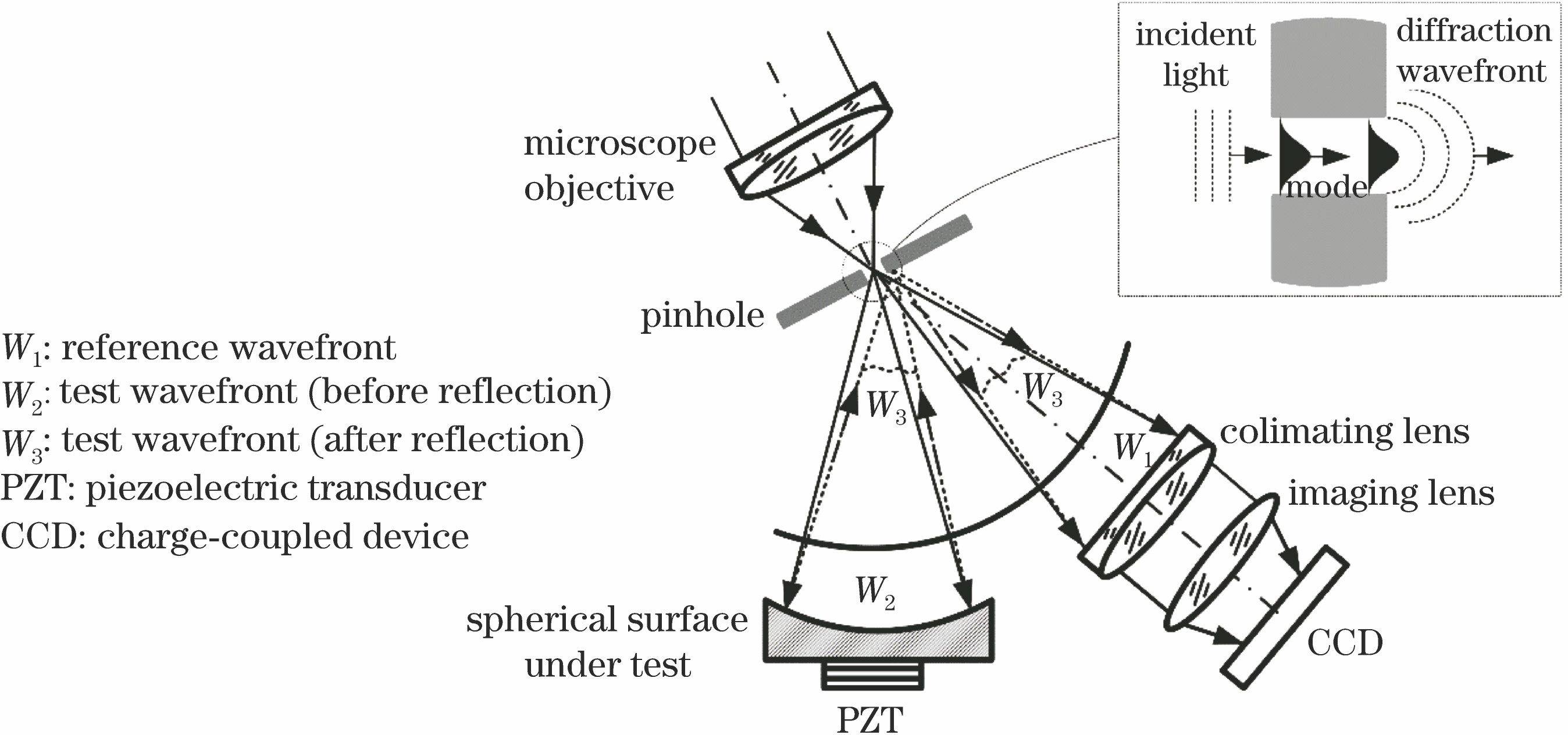
Fig. 1. Principle of pinhole point diffraction interferometer
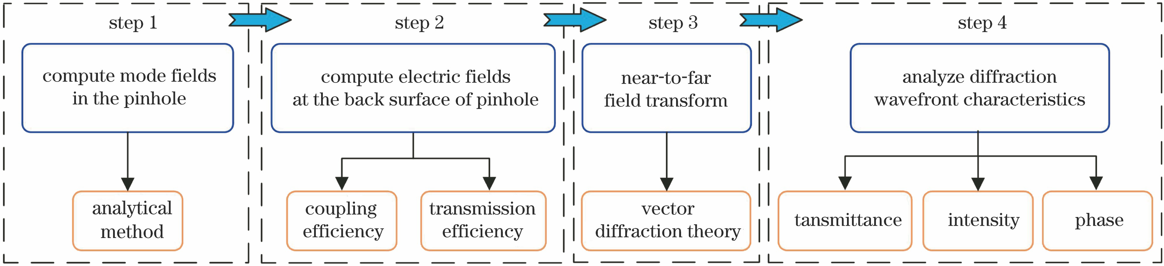
Fig. 2. Wavefront analysis method of pinhole point-diffraction based on waveguide theory
Fig. 3. Coordinate system of pinhole diffraction
Fig. 4. Electric field amplitude distribution of TE11 mode derived by analytical method. (a) Ex ; (b) Ey ; (c) Er ; (d) Eφ
Fig. 5. Electric field amplitude distribution at theback surface of pinhole derived by FDTD algorithm. (a) Ex ; (b) Ey ; (c) Er ; (d) Eφ
Fig. 6. Light transmittance of pinhole with different diameter
Fig. 7. Mode spectrum for pinhole
Fig. 8. Electric field amplitude distribution of mode in the pinhole. (a) TE11; (b) TE21; (c) TM01
Fig. 9. Intensity distribution of diffraction wavefront. (a) Pinhole diameter D =λ ; (b) pinhole diameter D =0.8λ ; (c) pinhole diameter D =1.4λ ; (d) cross section of intensity along different direction angle ?
Fig. 10. Phase distribution of electric field in the far field. (a) E ? ( far ) E
Fig. 11. Zernike polynomial fitting result. (a) Diffraction wavefront after fitting; (b) Zernike coefficients

Set citation alerts for the article
Please enter your email address
© Copyright 2018-2021 | Chinese Laser Press. All Rights Reserved 沪ICP备15018463号-20