• Photonics Research
  • Vol. 8, Issue 2, 165 (2020)
Li Shen1, Hao Wu1, Can Zhao1、*, Lei Shen2, Rui Zhang2, Weijun Tong2, Songnian Fu1, and Ming Tang1
Author Affiliations
  • 1Wuhan National Laboratory for Optoelectronics (WNLO) & National Engineering Laboratory for Next Generation Internet Access System, School of Optical and Electronic Information, Huazhong University of Science and Technology, Wuhan 430074, China
  • 2State Key Laboratory of Optical Fiber and Cable Manufacture Technology, Yangtze Optical Fiber and Cable Joint Stock Limited Company (YOFC) R&D Center, Wuhan 430073, China
  • show less
    DOI: 10.1364/PRJ.379178 Cite this Article Set citation alerts
    Li Shen, Hao Wu, Can Zhao, Lei Shen, Rui Zhang, Weijun Tong, Songnian Fu, Ming Tang. Distributed curvature sensing based on a bending loss-resistant ring-core fiber[J]. Photonics Research, 2020, 8(2): 165 Copy Citation Text show less
    (a) Optical microscope image of cross section of the RCF; (b) measured refractive index profile of the RCF; (c) simulated LP01, LP11, LP21, and LP31 mode groups supported by the RCF.
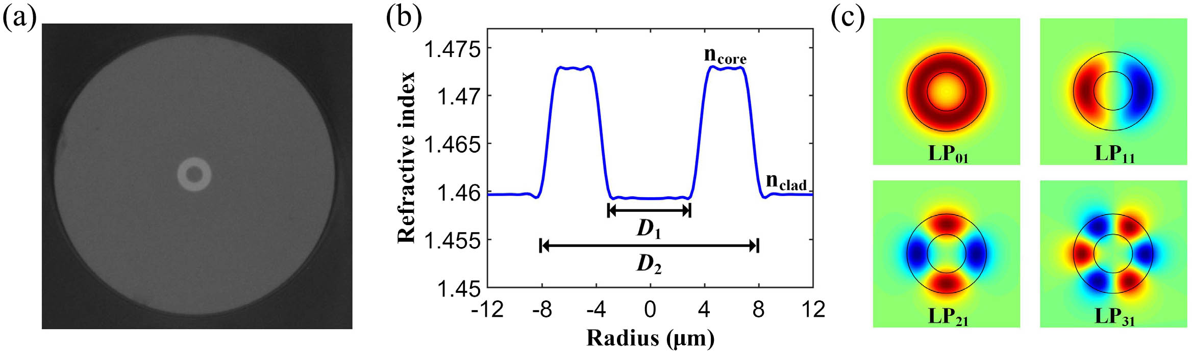
    Fig. 1. (a) Optical microscope image of cross section of the RCF; (b) measured refractive index profile of the RCF; (c) simulated LP01, LP11, LP21, and LP31 mode groups supported by the RCF.
    (a) Position-dependent strain induced by fiber bending; (b) strain distribution on the fiber cross section; (c) simulated optical mode field of the bent RCF.
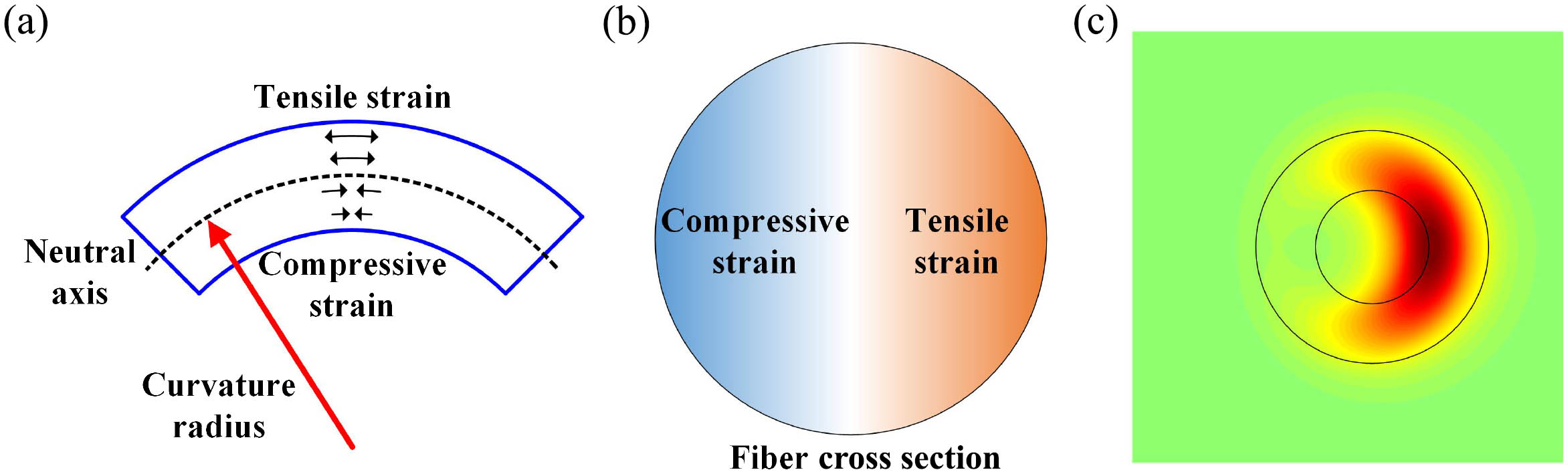
    Fig. 2. (a) Position-dependent strain induced by fiber bending; (b) strain distribution on the fiber cross section; (c) simulated optical mode field of the bent RCF.
    Experimental setup for the BOTDA system based on the RCF. PC, polarization controller; EOM, electro-optic modulator; MS, microwave synthesizer; SOA, semiconductor optical amplifier; AFG, arbitrary function generator; PS, polarization scrambler; EDFA, erbium-doped fiber amplifier; CIR, circulator; FBG, fiber Bragg grating; PD, photodetector; inset, measured far-field profile at the output end of the RCF when excited through an SMF.
    Fig. 3. Experimental setup for the BOTDA system based on the RCF. PC, polarization controller; EOM, electro-optic modulator; MS, microwave synthesizer; SOA, semiconductor optical amplifier; AFG, arbitrary function generator; PS, polarization scrambler; EDFA, erbium-doped fiber amplifier; CIR, circulator; FBG, fiber Bragg grating; PD, photodetector; inset, measured far-field profile at the output end of the RCF when excited through an SMF.
    (a) Measured BGS distribution along the RCF with a heated segment; (b) experimentally measured BGS and Lorentz fitting curve at the output end of the RCF.
    Fig. 4. (a) Measured BGS distribution along the RCF with a heated segment; (b) experimentally measured BGS and Lorentz fitting curve at the output end of the RCF.
    BFS as a function of (a) temperature and (b) strain for the RCF and the linear fitting results.
    Fig. 5. BFS as a function of (a) temperature and (b) strain for the RCF and the linear fitting results.
    (a) Schematic diagram of distributed curvature measurement by winding the RCF around plastic cylinders with different diameters; (b) measured BGS distribution along the bent RCF.
    Fig. 6. (a) Schematic diagram of distributed curvature measurement by winding the RCF around plastic cylinders with different diameters; (b) measured BGS distribution along the bent RCF.
    Measured fiber bending-induced (a) BFS and (b) peak Brillouin gain variation along the RCF.
    Fig. 7. Measured fiber bending-induced (a) BFS and (b) peak Brillouin gain variation along the RCF.
    Macrobending loss comparison between the RCF and the SMF.
    Fig. 8. Macrobending loss comparison between the RCF and the SMF.
    Simulated mode-field distributions of the bent RCF with different curvature radii.
    Fig. 9. Simulated mode-field distributions of the bent RCF with different curvature radii.
    Calculated power center shift and normalized effective area as functions of curvature radius.
    Fig. 10. Calculated power center shift and normalized effective area as functions of curvature radius.
    (a) Simulated bending-induced BFS change and experimental results; (b) simulated bending-induced peak Brillouin gain variation and experimental results.
    Fig. 11. (a) Simulated bending-induced BFS change and experimental results; (b) simulated bending-induced peak Brillouin gain variation and experimental results.
    (a) Comparison of BFS variation and measurement range for the RCF and FMFs; (b) comparison of measurement sensitivity for the RCF and FMFs.
    Fig. 12. (a) Comparison of BFS variation and measurement range for the RCF and FMFs; (b) comparison of measurement sensitivity for the RCF and FMFs.
    Bend-induced birefringence versus curvature radius.
    Fig. 13. Bend-induced birefringence versus curvature radius.
    (a) BFS change of the heated curved RCF with temperature; (b) Brillouin gain change of the heated curved RCF with temperature.
    Fig. 14. (a) BFS change of the heated curved RCF with temperature; (b) Brillouin gain change of the heated curved RCF with temperature.
    Estimated curvature radius based on the BFS and Brillouin gain.
    Fig. 15. Estimated curvature radius based on the BFS and Brillouin gain.
    Li Shen, Hao Wu, Can Zhao, Lei Shen, Rui Zhang, Weijun Tong, Songnian Fu, Ming Tang. Distributed curvature sensing based on a bending loss-resistant ring-core fiber[J]. Photonics Research, 2020, 8(2): 165
    Download Citation