1Wuhan National Laboratory for Optoelectronics (WNLO) & National Engineering Laboratory for Next Generation Internet Access System, School of Optical and Electronic Information, Huazhong University of Science and Technology, Wuhan 430074, China
2State Key Laboratory of Optical Fiber and Cable Manufacture Technology, Yangtze Optical Fiber and Cable Joint Stock Limited Company (YOFC) R&D Center, Wuhan 430073, China
Li Shen, Hao Wu, Can Zhao, Lei Shen, Rui Zhang, Weijun Tong, Songnian Fu, Ming Tang, "Distributed curvature sensing based on a bending loss-resistant ring-core fiber," Photonics Res. 8, 165 (2020)
Copy Citation Text
A theoretical and experimental study on curvature sensing using a Brillouin optical time-domain analyzer based on the ring-core fiber (RCF) is reported. The Brillouin gain spectrum of the RCF is investigated, and the Brillouin frequency shift (BFS) dependence on temperature and strain is calibrated. We theoretically analyze the fiber bending-induced BFS and peak Brillouin gain variation for the RCF through a numerical simulation method, and the RCF is revealed to have a high curvature sensitivity. Distributed curvature sensing is successfully demonstrated, with the bending radius ranging from 0.5 to 1.5 cm, corresponding to a BFS variation from 32.90 to 7.81 MHz. The RCF takes advantage of great bending loss resistance, and the maximum macrobending loss at the extreme bending radius of 0.5 cm is less than 0.01 dB/turn. Besides, the peak Brillouin gain of the RCF is discovered to vary significantly in response to fiber bending, which is expected to be another parameter for distributed curvature determination. The results imply that the RCF is a promising candidate for highly sensitive distributed curvature measurement, especially in sharp bending circumstances.
1. INTRODUCTION
In the past few decades, distributed optical fiber sensing has been extensively investigated due to advantages like compactness, low cost, and long sensing range. Importantly, it offers the possibility that one optical fiber can replace a large number of closely spaced point sensors [1–4]. As a typical Brillouin-based distributed fiber-sensing technology, the Brillouin optical time-domain analyzer (BOTDA) has become one of the most promising fiber-sensing technologies for its superior performance. The BOTDA is currently mainly applied to measuring distributed strain and temperature profiles along single-mode fibers (SMFs) [5–12]. With the rapid development of specialty optical fibers, BOTDA systems have been recently researched based on various other kinds of fibers, such as photonic crystal fibers (PCFs) [13,14], polymer optical fibers (POFs) [15], few-mode fibers (FMFs) [16–20], and multicore fibers (MCFs) [21,22].
Compared with conventional SMFs, the specialty optical-fiber-based BOTDA systems show unique advantages in measuring physical quantities besides temperature and strain, one of which is the distributed curvature. Distributed curvature sensing is now widely demanded in a variety of applications, such as surgical instruments [23], microelectronic systems [24], and structural health monitoring [25]. As is known, the Brillouin frequency shift (BFS) of SMFs shows weak dependence on fiber bending [26]. In addition, the fiber macrobending loss of SMFs will increase sharply as the curvature radius decreases. Thus, the bending loss of SMFs is widely utilized for point microbend sensors, which can achieve a minimum detectable curvature radius of 0.3 cm [27], but it suffers from the signal-to-noise ratio (SNR) reduction, especially for multipoint or distributed curvature measurement. It has been reported that bending-induced BFS variation is much larger in FMF compared with SMF. And the FMF-based BOTDA has achieved distributed curvature measurement with bending radii ranging from 0.9 to 2.7 cm [17]. It has also been demonstrated that for BOTDA systems based on the MCF, both the bending angle and radius can be retrieved by using signals from multiple cores in the same cladding, which establishes a foundation to perform distributed three-dimensional shape determination [21]. However, for the fibers mentioned above, the minimum measurable bending radius is severely limited by fiber macrobending loss. In this case, a kind of specialty optical fiber with an excellent bending loss resistance is essential for distributed curvature measurement.
The ring-core fiber (RCF) is another kind of specialty optical fiber that has been studied primarily in mode-division multiplexing (MDM) transmission systems [28–32]. It is a type of FMF with a ring core around a fiber center. To the best of our knowledge, distributed sensing capabilities offered by the RCF have never yet been exploited. Previous studies suggest that the RCF has an extraordinary bending resistance, and the macrobending loss is much smaller than that of the SMF [28,33]. It is therefore expected that the RCF can be a suitable candidate for curvature measurement.
Sign up for Photonics Research TOC. Get the latest issue of Photonics Research delivered right to you!Sign up now
In this work, BOTDA-based distributed curvature sensing by exploiting the RCF is investigated. First, the BFS dependence on temperature and strain for the RCF is measured, which is slightly smaller than that of the SMF. For the bent RCF, the optical mode deformation within the bending fiber is quantitatively analyzed with a numerical simulation method. Simulation results demonstrate that the optical mode field will shift away from the fiber neutral axis and undergo a tensile strain. More particularly, the peak Brillouin gain is found to increase in the bent RCF region due to the decreased optical mode effective area, which may provide another measurement parameter for curvature determination. After that, the distributed curvature measurement based on the RCF is conducted with a bending radius range from 0.5 to 1.5 cm. The maximum bending loss is measured to be less than 0.01 dB/turn. In the experiment, both BFS and peak Brillouin gain change significantly with varying curvature radii, as the simulation implies. The maximum BFS variation at a bending radius of 0.5 cm is about 32.9 MHz. At the same time, the peak Brillouin gain is almost doubled compared to that in the straight RCF. Experimental results indicate that the RCF has a much higher bending response compared with the SMF, in addition to its excellent macrobending loss resistance. These features enable the RCF to be an appropriate candidate for distributed curvature sensing with extreme bending conditions.
2. FIBER PARAMETERS AND THE PRINCIPLE OF CURVATURE SENSING
In a BOTDA system, usually a low-frequency probe light and a high-frequency counterpropagating pump pulsed light are launched into the sensing fiber, and optical power will transfer from the pump light to the probe light through the stimulated Brillouin scattering (SBS) process. When the frequency offset between the pump and probe light approaches the local BFS of the fiber, the transferred power reaches a maximum that corresponds to a peak Brillouin gain. At location along the fiber, the peak Brillouin gain of probe light can be given by [34] where is the Brillouin signal power, is the probe light power in absence of SBS interaction, is the Brillouin gain factor for the given frequency offset at BFS, is the effective area of the guided optical mode, is the pump pulse power, and is the interaction length between pump and probe light. Considering that the BOTDA system operates in the small gain regime, Eq. (1) can be simplified as
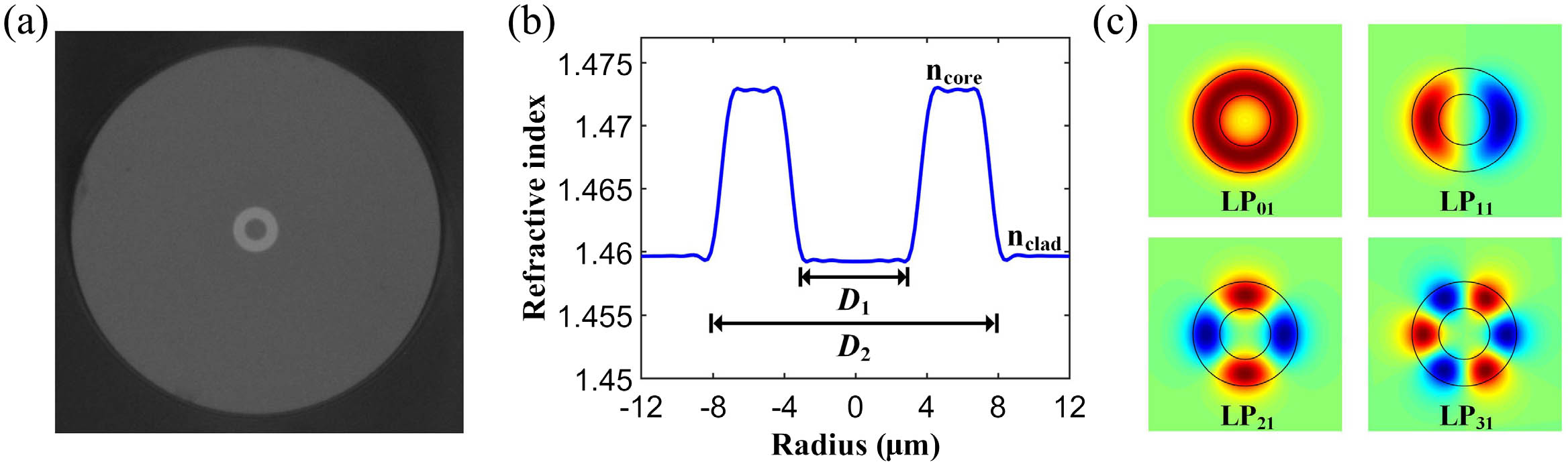
The fiber we used for the BOTDA is an RCF (manufactured by YOFC). Figure 1(a) shows the optical microscope image of the fiber cross section, where the bright ring-structured core can be observed. The measured step refractive index profile of the RCF is shown in Fig. 1(b). The RCF has an inner core diameter () of 7.38 μm, an outer core diameter () of 15.14 μm, and a cladding diameter of 125 μm. The refractive indices of core () and cladding () are 1.4728 and 1.4597, respectively. As shown in Fig. 1(c), , , , and mode groups are supported by the RCF in the C band with attenuation of 0.29, 0.29, 0.31, and 0.32 dB/km, respectively [28]. Differential group delay (DGD) for , , and modes is 3.9, 11.0, and 18.2 ps/m, respectively [28]. Mode-field distributions are simulated by the finite-element method (FEM) using the commercial software COMSOL, and the simulated effective refractive index (ERI) for , , , and modes is 1.4683, 1.4674, 1.4653, and 1.4621, respectively. In the experiment, only the fundamental mode is effectively excited and characterized for the BOTDA system.
Figure 1.(a) Optical microscope image of cross section of the RCF; (b) measured refractive index profile of the RCF; (c) simulated , , , and mode groups supported by the RCF.
The mechanism of distributed curvature sensing using the RCF is theoretically analyzed as follows. As shown in Fig. 2(a), the fiber bending will introduce a position-dependent strain [26,35]. The strain is zero at the fiber neutral axis. One side of the RCF above the neutral axis will be affected by tensile strain, and the opposite side will be affected by compressive strain. As shown in Fig. 2(b), on the fiber cross section, strain distribution is given by [26,35] where is the distance from the fiber neutral axis taken along the bending direction, and is the curvature radius. Tensile strain corresponds to positive , and compressive strain corresponds to negative .
Figure 2.(a) Position-dependent strain induced by fiber bending; (b) strain distribution on the fiber cross section; (c) simulated optical mode field of the bent RCF.
Fiber bending will also induce a perturbation on the refractive index profile over the RCF cross section, thus leading to mode-field deformation [36]. Based on the method of conformal mapping [37] and FEM simulation, the mode field for the bent RCF with a curvature radius of 0.5125 cm is analyzed, and the simulated ERI is 1.4691. As shown in Fig. 2(c), when the RCF bends, the mode field not only shifts away from the neutral axis and concentrates on the tensile region, but also changes substantially in transverse distribution. As a consequence, the shifted mode field is under an overall bending-induced tensile strain in the bent RCF; thus the BFS is predicted to increase. At the same time, the distorted mode field has a decreased effective mode area, which may produce a higher peak Brillouin gain according to Eq. (2). To verify these properties, distributed curvature measurement is carried out in the following section.
3. EXPERIMENTAL SETUP AND RESULTS
The experimental setup employed in this work is illustrated in Fig. 3. An external-cavity laser operating near 1550 nm is used as the optical source. The light source is split into pump and probe branches by a 50:50 optical coupler. The probe light in the upper path is first modulated by an electro-optic modulator (EOM), which is driven by a microwave synthesizer (MS) to generate two sidebands through carrier-suppressed double-sideband modulation [38]. The modulated probe light is then fed into the RCF through an isolator. The lower path pump light is modulated by a semiconductor optical amplifier (SOA) driven by an arbitrary function generator (AFG) to acquire high extinction ratio optical pulses, with a pulse width of 50 ns, a repetition rate of 50 kHz, and an extinction ratio beyond 50 dB. A polarization scrambler (PS) is used to change the polarization state of the pump pulse light randomly. Each signal trace is averaged for 512 times in the experiment to reduce signal fluctuation caused by polarization-fading and to improve the SNR. The pump light is then amplified by an erbium-doped fiber amplifier (EDFA) with an output average power of and is fed into the RCF through an optical circulator (CIR). At the receiver side, the Brillouin-amplified probe light passes through a fiber Bragg grating (FBG) to mitigate the unwanted higher-frequency sideband, and is then received by a photodetector (PD) with a bandwidth of 125 MHz. The electrical signals of the PD are sampled by an oscilloscope with a sampling rate of 1 GSa/s. The moving average algorithm is applied to the received signal to improve the SNR [39,40]. By controlling the microwave frequency that drives the EOM, frequency offset between the pump and probe lights is scanned from 10.25 to 10.55 GHz, with a step size of 1 MHz.
Figure 3.Experimental setup for the BOTDA system based on the RCF. PC, polarization controller; EOM, electro-optic modulator; MS, microwave synthesizer; SOA, semiconductor optical amplifier; AFG, arbitrary function generator; PS, polarization scrambler; EDFA, erbium-doped fiber amplifier; CIR, circulator; FBG, fiber Bragg grating; PD, photodetector; inset, measured far-field profile at the output end of the RCF when excited through an SMF.
In the experiment, to selectively excite the fundamental mode, both ends of the RCF are center-aligned and spliced with SMFs. The total loss of a 134 m RCF after splicing is 3.711 dB, which is mainly caused by the mode-field mismatch between the RCF and SMF. Taper splicing and other techniques may be applied further to reduce the splicing loss between the RCF and SMF [17]. The inset of Fig. 3 shows the far-field profile captured by a CCD camera at the output end of the RCF when excited through an SMF, where the ring shape near-field profile evolves into a Gaussian shape in the far field [28]. The circular shape distribution of the far-field profile indicates that the fundamental mode is dominant after fiber transmission, and other higher-order modes in the RCF are effectively suppressed by precisely aligning the RCF with the center of the SMF.
First, the Brillouin gain spectrum (BGS) distribution of the RCF is measured, and its response to temperature and strain is characterized. To study the temperature sensitivity of the RCF, a 14 m segment at the far end is immersed in a temperature-controlled water-bath pot. Distributed measurement is performed with a pulse width of 50 ns, which corresponds to a spatial resolution of 5 m. Figure 4(a) shows the measured BGS distribution along the RCF, where an increase in BFS at the heated segment can be observed. The Lorentz fitting curve is applied to the BGS based on the least-squares fitting method. Figure 4(b) shows the experimentally measured BGS and the Lorentz fitting curve at the output end of the RCF. The estimated BFS is about 10.403 GHz at room temperature, and the full width at half-maximum (FWHM) of the BGS is about 46.4 MHz.
Figure 4.(a) Measured BGS distribution along the RCF with a heated segment; (b) experimentally measured BGS and Lorentz fitting curve at the output end of the RCF.
The BFS change of the RCF with temperature from 40.5°C to 61°C is shown in Fig. 5(a). The estimated temperature coefficient is 0.9024 MHz/°C with linear fitting to the experimental results. Then the strain sensitivity of the RCF is calibrated. The pump pulse width is changed to 20 ns, which corresponds to a 2 m spatial resolution. A 2.2 m segment at the far end of the RCF is fixed on translation stages, and the strain is applied by moving the translation stages to stretch the RCF. Figure 5(b) shows the measured BFS as a function of applied strain. The calculated strain coefficient is 0.04111 MHz/με with linear fitting. Both the temperature and strain coefficients of the RCF are slightly smaller than those of a typical SMF [41].
Figure 5.BFS as a function of (a) temperature and (b) strain for the RCF and the linear fitting results.
Next, the distributed curvature measurement of the RCF is performed. As shown in Fig. 6(a), we wind a segment of the RCF around different plastic cylinders. We take care to avoid axial tension to the RCF during the winding process. Diameters of the plastic cylinders are 1, 1.5, 2, and 3 cm, respectively. Considering that the coating diameter of the RCF is 250 μm, the actual curvature radii are 0.5125 cm (), 0.7625 cm (), 1.0125 cm (), and 1.5125 cm (), respectively. Cylinder diameters are chosen in this range because the BFS change will be too faint to distinguish using cylinders with a larger diameter, and it is challenging to wind several meters of RCF around thinner cylinders. Figure 6(b) shows the measured BGS distribution along the RCF. As expected, both BFS and peak Brillouin gain change accordingly with the curvature radius in the bending area. Four segments can be distinguished, each of which corresponds to a cylinder of a specific diameter.
Figure 6.(a) Schematic diagram of distributed curvature measurement by winding the RCF around plastic cylinders with different diameters; (b) measured BGS distribution along the bent RCF.
To comprehensively characterize the BGS response in bent RCF, the BFS and peak Brillouin gain are analyzed separately. The measured distributed BFS along the bent RCF is shown in Fig. 7(a). The BFS distribution has four uniform segments in the bending area, corresponding to the curvature radius of to , respectively. Out of the fiber bending segments are straight loose RCFs for reference. The standard deviation of BFS for the straight RCF is calculated as BFS uncertainty, and the calculated BFS resolution is 0.3551 MHz without any denoising algorithm. The SNR at the fiber end is about 17.9 dB; thus, we believe it can be applied to long-range distributed sensing. The average BFS variation of each segment is 32.90, 21.94, 14.39, and 7.81 MHz, respectively. The FWHM of the BGS is 70.7202, 68.8378, 68.5212, and 69.2687 MHz for curvature radius to , respectively. And for the straight area the FWHM of the BGS is 66.1462 MHz with pump pulse width of 20 ns. The slight broadening of the BGS linewidth along the bending area may be due to the combined effects of Brillouin gain and phonon decay rate variation [42]. The BFS variation of the RCF shows a significantly higher dependence on curvature radius compared with the SMF. The BFS change is about 1.27 MHz, with a curvature radius of 1.5125 cm for the SMF [26], while the BFS change of RCF is as high as 7.81 MHz. Meanwhile, the measured distributed peak Brillouin gain along the bent RCF also consists of four segments, as shown in Fig. 7(b). Notably, the peak Brillouin gain of the RCF at the bending radius of 0.5125 cm is almost 2 times that of the straight parts. The peak Brillouin gain variation at each bending section could be attributed to imperfect polarization averaging. It can be seen that the peak Brillouin gain before and after the bending segments keeps consistent, illustrating that the RCF can effectively resist signal loss induced by extreme bending.
Figure 7.Measured fiber bending-induced (a) BFS and (b) peak Brillouin gain variation along the RCF.
To further investigate the macrobending loss characteristics, we wind the RCF and a standard G.652.D SMF onto cylinders with different diameters and measure the loss. As shown in Fig. 8, the RCF shows a much higher bending resistance, and the macrobending loss is significantly smaller than that of the SMF for all measured curvature radii. The macrobending loss of the SMF is as high as 18.4 dB/turn at the curvature radius of 0.5125 cm, while the loss of the RCF is less than 0.01 dB/turn. The low macrobending loss of the RCF will ensure the SNR for the BOTDA system and sustain the minimum curvature radius that can be measured.
Figure 8.Macrobending loss comparison between the RCF and the SMF.
In order to quantify the BFS and peak Brillouin gain variation resulting from fiber bending, the mode field in the bent RCF is numerically analyzed using the FEM. The simulated mode-field distributions with increased curvature radius are shown in Fig. 9. First, the lateral shift of the mode field is calculated. For the bent SMF, the lateral shift from the fiber neutral axis can be represented by the offset of the maximum mode-field intensity when the cross-section distribution is maintained [36]. However, as for the bent RCF, in addition to the lateral shift, there is significant mode-field distortion. Thus, we propose to use the power center shift to indicate the mode-field shift. The power center shift is calculated by where is the power density distribution of the guided optical mode at the fiber cross section. is the distance from the power-averaged center to the neutral axis, which can reflect the overall shift distance of the mode field. The calculated relation between the power center shift and curvature radius for the bent RCF is shown as the red line in Fig. 10. The mode field gradually shifts away from the neutral axis with the decrease in the curvature radius. We also simulate the change of effective area caused by fiber bending. In the straight RCF, the simulated effective area is μ. The blue line in Fig. 10 shows that the effective area decreases with the reduced curvature radius in the bent RCF. The results are normalized by the effective area in the straight RCF.
Figure 9.Simulated mode-field distributions of the bent RCF with different curvature radii.
With simulation results of the power center shift and effective area change, we can further study the BFS and peak Brillouin gain variation accordingly. The bending-induced strain is approximated by the strain at the power-averaged center. By combining Eqs. (3) and (4), the theoretical BFS variations with the curvature radius can be expressed by
Using the measured strain coefficient and simulated power center shift , the calculated relation between BFS change and curvature radius is derived [see Fig. 11(a)]. The simulation results agree well with the experimental data, indicating that our proposed method can reasonably simulate the BFS change for the bent RCF and offer a reliable support for practical applications of the RCF in curvature sensing.
Figure 11.(a) Simulated bending-induced BFS change and experimental results; (b) simulated bending-induced peak Brillouin gain variation and experimental results.
According to Eq. (2), the peak Brillouin gain is inversely proportional to the effective area; thus, it can be easily calculated. The simulated peak Brillouin gain variation and experimental results are shown in Fig. 11(b). The experimental results are normalized by the peak Brillouin gain in the straight RCF. The peak Brillouin gain presents an evident trend of rising with a smaller curvature radius, which implies that it provides an additional parameter for distributed curvature measurement. The experimental data are slightly smaller than the simulation results, which can be attributed to the decrease in the local Brillouin gain factor . is directly proportional to the overlap between the acoustic mode and optical modes, which may decrease inside the bent RCF. Further study about the acoustic mode in the bent RCF is needed for precise evaluation of the peak Brillouin gain.
The measurement range and sensitivity of the RCF are compared with other FMFs. Step-index four-mode FMFs with core diameters of 20.6 and 18 μm have been demonstrated for distributed curvature measurement [17,18]. In Fig. 12(a), the simulated BFS variation related to curvature radius for the RCF is compared with the fitting results of FMFs. The minimum detectable curvature radius for FMFs is about 0.9 cm, which is restricted by macrobending loss, while the RCF has a much smaller minimum detectable curvature radius of 0.5 cm. The bending sensitivity can be obtained by taking the derivative of BFS change with respect to curvature radius. Figure 12(b) shows the bending sensitivity of the RCF and FMFs. The curvature sensitivity of the RCF is comparable to an FMF with a core diameter of 18 μm and is much more sensitive at a small curvature radius. Combined with its great bending loss resistance, the results indicate that the RCF is a suitable candidate for curvature measurement with a sharp bending radius.
Figure 12.(a) Comparison of BFS variation and measurement range for the RCF and FMFs; (b) comparison of measurement sensitivity for the RCF and FMFs.
It should be noted that birefringence can result from extreme bending conditions; thus, its effect on BFS variation should be carefully studied. Birefringence is known as the ERI difference in the and polarization modes, which can be calculated as [43] where and refer to the ERI of the and polarization modes, respectively. Figure 13 shows the calculated birefringence of the RCF as a function of curvature radius. It can be observed that birefringence increases with the reduced curvature radius, and the simulated birefringence is at a curvature radius of 0.5125 cm.
Figure 13.Bend-induced birefringence versus curvature radius.
Based on the phase-matching condition of SBS, the variation of BFS caused by fiber birefringence can be qualitatively evaluated by [44] where () and () are the wavelength and ERI of the pump (probe), and is the phase velocity of the acoustic mode. Bending-induced birefringence will cause a variance of on and , depending on the polarization state, and the resulting BFS variation is about 0.1 MHz, based on Eq. (7). Thus, the effect of birefringence on BFS can be safely ignored for the RCF.
5. DISCUSSION
The insensitivity of the Brillouin gain to temperature variance can improve the curvature measurement accuracy under a temperature-changing environment. To quantitatively analyze the influence of temperature on curvature measurement, a segment of the RCF around a plastic cylinder with a diameter of 1.5 cm is immersed in a temperature-controlled water-bath pot, with the rest of the RCF kept at a room temperature of 23°C. Using the straight loose RCF at room temperature as a reference, the BFS change and normalized peak Brillouin gain of the heated curved segment are observed; see Figs. 14(a) and 14(b), respectively. BFS changes linearly with temperature with a coefficient of 0.924 MHz/°C. The Brillouin gain has the tendency to increase with temperature, and the irregular change could be caused by imperfect polarization averaging.
Figure 14.(a) BFS change of the heated curved RCF with temperature; (b) Brillouin gain change of the heated curved RCF with temperature.
Figure 15 shows the estimated curvature radius based on the BFS and Brillouin gain. The corresponding curvature radius can be accurately estimated from BFS change through a simulated relation result, or recovered from Brillouin gain by the quadratic fitting curve of experimental results. Due to the additional BFS change caused by temperature, the estimated curvature radius will decrease dramatically with increased temperature. However, the peak Brillouin gain is relatively insensitive to temperature, and curvature radius can be more accurately estimated. The results indicate that the use of peak Brillouin gain can reduce the influence of temperature change to improve the accuracy of curvature radius measurement.
Figure 15.Estimated curvature radius based on the BFS and Brillouin gain.
We have proposed and demonstrated a BOTDA system based on the RCF for the distributed curvature sensing for what we believe is the first time. First, a thorough experimental investigation on temperature and strain coefficients of the RCF has been reported. More importantly, a distributed curvature sensing has been demonstrated, with a radius ranging from 0.5 to 1.5 cm. The maximum BFS variation at a bending radius of 0.5 cm is about 32.9 MHz. In addition, the peak Brillouin gain of the RCF also presents a high response to fiber bending, which is about 2 times larger at a bending radius of 0.5 cm than that in straight RCFs. For a quantitative study, we propose a numerical method to evaluate the BFS and peak Brillouin gain variation caused by fiber bending. The simulation results are in good agreement with those in experiments.
The proposed RCF-based BOTDA system exhibits some unique advantages in distributed curvature measurement. First of all, the BFS of the RCF has a much higher sensitivity to curvature variation compared with SMFs. Moreover, the peak Brillouin gain shows a distinctive characteristic of curvature sensing, whose insensitivity to temperature and axial strain variance can eliminate the environmental influence on measurement accuracy. At last, the RCF is of excellent bending loss resistance, which enables it to carry out distributed curvature sensing with extreme bending radius. Overall, we believe that RCF can be widely deployed in fields for highly sensitive curvature monitoring applications.
[24] Shape sensing of miniature snake-like robots using optical fibers. IEEE/RSJ International Conference on Intelligent Robots and Systems (IROS), 947-952(2017).
[42] Brillouin linewidth characterization in single mode large effective area fiber through the co-pumped technique. Int. J. Electron. Comput. Commun. Technol., 1, 16-20(2010).
Li Shen, Hao Wu, Can Zhao, Lei Shen, Rui Zhang, Weijun Tong, Songnian Fu, Ming Tang, "Distributed curvature sensing based on a bending loss-resistant ring-core fiber," Photonics Res. 8, 165 (2020)