• Chinese Optics Letters
  • Vol. 16, Issue 5, 050005 (2018)
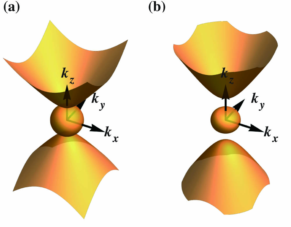
Dongyang Wang1、2, Jiaguang Han2, and Shuang Zhang1、2、*
Author Affiliations
  • 1School of Physics & Astronomy, University of Birmingham, Birmingham B15 2TT, UK
  • 2Center for Terahertz Waves and College of Precision Instrument and Optoelectronics Engineering, Tianjin University, Tianjin 300072, China
  • show less
    DOI: 10.3788/COL201816.050005 Cite this Article Set citation alerts
    Dongyang Wang, Jiaguang Han, Shuang Zhang. Optical cavity resonance with magnetized plasma[J]. Chinese Optics Letters, 2018, 16(5): 050005 Copy Citation Text show less
    EFS of magnetized plasma at f=0.4 THz, for (a) B=4 T and (b) B=0.4 T. The magnetic field is along the z direction and the parameters used in the calculation are the plasma frequency ωp/2π=0.5 THz, ε∞=16, and γ=5×10¹⁰ rad/s.
    Fig. 1. EFS of magnetized plasma at f=0.4THz, for (a) B=4T and (b) B=0.4T. The magnetic field is along the z direction and the parameters used in the calculation are the plasma frequency ωp/2π=0.5THz, ε=16, and γ=5×10¹⁰rad/s.
    (a) Top: 2D dispersion relation curve for f=0.4 THz on the kx=0 plane, and the selected wavevector value as marked on the curve: (ky,kz)∈{(3,5.68),(4,6.69),(5,7.80),(6,8.97),(7,10.18)}. Bottom: schematic of the 2D cavity array. (b) In-plane electric field Ey distribution of the cavities at the resonance frequency with Ez incidence, the cavity sizes are from left to right (ly,lz)∈{(125,66),(94,56),(75,48),(63,42),(54,37)} μm, corresponding to the wavevector coordinate in (a); the resonant mode orders used to determine the cavity sizes are (m,n)=(1,1). (c) The transmission spectra of different cavities around the resonance frequency corresponding to mode orders (m,n)=(1,1).
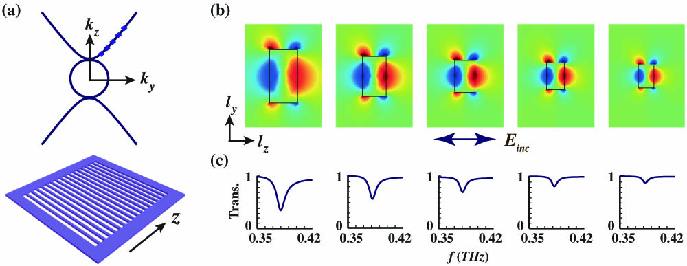
    Fig. 2. (a) Top: 2D dispersion relation curve for f=0.4THz on the kx=0 plane, and the selected wavevector value as marked on the curve: (ky,kz){(3,5.68),(4,6.69),(5,7.80),(6,8.97),(7,10.18)}. Bottom: schematic of the 2D cavity array. (b) In-plane electric field Ey distribution of the cavities at the resonance frequency with Ez incidence, the cavity sizes are from left to right (ly,lz){(125,66),(94,56),(75,48),(63,42),(54,37)}μm, corresponding to the wavevector coordinate in (a); the resonant mode orders used to determine the cavity sizes are (m,n)=(1,1). (c) The transmission spectra of different cavities around the resonance frequency corresponding to mode orders (m,n)=(1,1).
    (a) Resonance frequency shift with increasing mode number m when n is set to 1 for a cavity size of P1(200 μm,100 μm). (b) The resonance frequency shift with n increasing and m is set to 1 for a cavity size of P2(150 μm,200 μm). (c) The transmission spectrum for the case of (a). (d) The transmission spectrum for the case in (b). (e), (f) The configuration and the electric field distribution of different resonance frequencies in (c) and (d), with separate polarizations of Ey and Ez.
    Fig. 3. (a) Resonance frequency shift with increasing mode number m when n is set to 1 for a cavity size of P1(200μm,100  μm). (b) The resonance frequency shift with n increasing and m is set to 1 for a cavity size of P2(150  μm,200  μm). (c) The transmission spectrum for the case of (a). (d) The transmission spectrum for the case in (b). (e), (f) The configuration and the electric field distribution of different resonance frequencies in (c) and (d), with separate polarizations of Ey and Ez.
    (a) Transmission spectra for a fixed cavity size of (ly,lz)=(125 μm,66 μm) under different magnetic field strengths, with the same configuration as in Fig. 2. (b) The dependence of the cavity resonance frequency over the magnetic field for mode (1,1), where the solid line is calculated by using Eqs. (1) and (3), and the squares are obtained from the full wave simulation.
    Fig. 4. (a) Transmission spectra for a fixed cavity size of (ly,lz)=(125μm,66μm) under different magnetic field strengths, with the same configuration as in Fig. 2. (b) The dependence of the cavity resonance frequency over the magnetic field for mode (1,1), where the solid line is calculated by using Eqs. (1) and (3), and the squares are obtained from the full wave simulation.
    Dongyang Wang, Jiaguang Han, Shuang Zhang. Optical cavity resonance with magnetized plasma[J]. Chinese Optics Letters, 2018, 16(5): 050005
    Download Citation