Indefinite media with mixed signs of dielectric tensor elements possess unbounded equifrequency surfaces that have been utilized for diverse applications such as superimaging, enhanced spontaneous emission, and thermal radiation. One particularly interesting application of indefinite media is an optical cavity supporting anomalous scaling laws. In this Letter, we show that by replacing an indefinite medium with magnetized plasma one can construct a tunable indefinite cavity. The magnetized plasma model is based on realistic semiconductor material properties at terahertz frequencies that show hyperbolic dispersion in a certain frequency regime. The hyperbolic dispersion features are utilized for the design of optical cavities. Dramatically different sizes of cavities can support the same resonance mode at the same frequency. For a cavity of fixed size, the anomalous scaling law between the resonance frequency and mode number is confirmed. The resonance frequency can be strongly modulated by changing the strength of the applied magnetic field. The proposed model provides active controllability of terahertz resonances on the deep subwavelength scale with realistic semiconductor materials.
Optical cavities possess the ability to confine optical waves in a definite volume. They have attracted numerous studies and facilitated various applications such as energy harvesting, sensing, wavelength filtering, lasers, strong light-matter interaction, cavity quantum electrodynamics, wave chaos, and opto-mechanics[1–10]. For increasing the energy density in the cavity and achieving stronger light-matter interaction, higher quality factor and smaller size are desired. Some novel schemes have been proposed to achieve superior cavity performance, such as toroid-shaped cavities, photonic crystal defect cavities, and bound states in a continuum in photonic crystals[11–14].
Recently, indefinite media with hyperbolic dispersion have drawn growing attention due to their applications in superimaging, negative refraction, enhanced spontaneous emission, and thermal radiation[15–18]. Since the unbounded equal frequency surface (EFS) in indefinite media enables wave propagation with very large wavevectors, a cavity made of an indefinite medium can have a significantly reduced mode volume compared to conventional cavities. Interestingly, these cavities support anomalous scaling laws, which have been demonstrated by using hyperbolic metamaterials[19,20]. However, for broader applications, it is highly desired to have tunable optical cavities, whereas the metamaterial-based cavities have a fixed optical response once fabricated. Here we propose a reconfigurable way for achieving indefinite cavities by using magnetized plasma based on realistic semiconductor properties, and we study the corresponding scaling law governing the mode dispersion of such cavities.
Magnetized plasma has provided a platform for many interesting types of physical phenomena such as subwavelength imaging, chiral edge mode propagation, and photonic Weyl degeneracy[21–23]. The magnetized plasma considered here is based on a realistic semiconductor—InSb (indium antimonide), under a magnetic field that can be readily realized in experiments. Benefitting from the extremely small effective mass of electrons in InSb, a moderately high magnetic field can lead to a very large cyclotron frequency that exceeds the plasma frequency, resulting in dispersion sharing some similarity to that of hyperbolic media. The EFS of magnetized InSb can be dynamically controlled by tuning either the magnetic field strength or the temperature, leading to a strong variation of the dispersion of the cavity medium.
Sign up for Chinese Optics Letters TOC. Get the latest issue of Chinese Optics Letters delivered right to you!Sign up now
The electromagnetic properties of magnetized plasma can be obtained by taking into account both the Drude model and Lorentz force arising from the magnetic field. For an applied magnetic field in the direction, the electron motion along the direction is not affected, and therefore the permittivity component along the direction is still described by the Drude model. However, the motion of electrons in the and directions is coupled to each other by the Lorentz force, leading to the presence of an off-diagonal element in the in-plane directions. The permittivity tensor of magnetized plasma is given as with , , and , where is the plasma frequency, is the cyclotron frequency, and is the damping factor. For an extremely strong magnetic field, i.e., the cyclotron frequency approaches infinity, the permittivity tensor approaches that of an ideal hyperbolic medium, with , , and . On the other hand, for finite cyclotron frequencies, the propagation of a wave along the direction is not degenerate, leading to different dispersions for left handed and right handed circular polarizations (LCPs and RCPs), and consequently a gap between the hyperbolic EFS and the elliptical one in the momentum space.
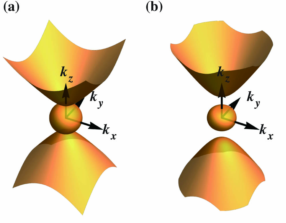
We begin with a very strong magnetic field of 4 teslas (T), which leads to a much larger cyclotron frequency than the plasma frequency and an approximate hyperbolic dispersion. The dispersion can be rigorously calculated by solving the Maxwell equations, which leads to the expression[21]where , , and . For frequencies below the plasma frequency, we can see that there are two branches of EFSs in Fig. 1(a), an unbounded EFS showing hyperbolic features and a closed surface. This is very similar to a typical type I hyperbolic medium, with the exception that there is a very tiny gap between the two EFSs due to the magneto-optical effect that breaks down the degeneracy between LCP and RCP along the direction. When the applied magnetic field is reduced to 0.4 T, the cyclotron frequency is around 0.7 THz, which is slightly greater than the plasma frequency. The resulting isosurface at deviates significantly from that of hyperbolic media, and there exists a much larger gap between the two circularly polarized states.
Figure 1.EFS of magnetized plasma at , for (a) and (b) . The magnetic field is along the direction and the parameters used in the calculation are the plasma frequency , , and .
Next, we consider a two-dimensional (2D) cavity made from InSb under a magnetic field of 4 T along the direction, as shown in Fig. 2(a). Since , by neglecting the damping factor the isosurface is very close to that of a hyperbolic medium, which is given by
Figure 2.(a) Top: 2D dispersion relation curve for on the plane, and the selected wavevector value as marked on the curve: . Bottom: schematic of the 2D cavity array. (b) In-plane electric field distribution of the cavities at the resonance frequency with incidence, the cavity sizes are from left to right μ, corresponding to the wavevector coordinate in (a); the resonant mode orders used to determine the cavity sizes are . (c) The transmission spectra of different cavities around the resonance frequency corresponding to mode orders .
By setting , we have the 2D dispersion curves shown in Fig. 2(a). Each of the points on the dispersion curve corresponds to a possible electromagnetic field pattern. For simplicity, we first consider a perfect electric conductor (PEC) boundary for the cavity where the tangential component of the electric field vanishes. For a given frequency, the cavity sizes (, ) corresponding to a certain resonance with mode order (, ) are expressed as where the subscript is the direction along the applied magnetic field, the subscript is the direction perpendicular to it, and and are the resonant mode orders along the two directions, respectively.
We first consider the dispersion relation for the case of , which is below the plasma frequency, with the magnetic field maintained at 4 T. For several points taken from the hyperbolic band of the 2D EFSs, marked in Fig. 2(a), we calculate the approximate cavity sizes based on Eq. (3) for the mode orders . To verify the cavity resonance behavior, we simulate an array of cavities periodically arranged along the direction surrounded by air, and the period is set as three times of the cavity width . The incident terahertz wave has a polarization along the direction. The transmission spectra are shown in Fig. 2(c), where we can see that all the cavities of different sizes are resonant at approximately the same frequency, as expected. As we can see, as the size of cavities decreases, the absorption strength becomes weaker due to the larger momentum mismatch between the free space wave and the resonance mode in the cavity. The profile of the component of the electric field is shown in Fig. 2(b) for each cavity size. From the figure, we can easily identify the resonance mode order from the electric field distribution as , which is consistent with what is used to calculate the cavity sizes. It can be noted that the simulated resonance frequency slightly deviates from the calculation based on Eq. (3), due to the assumption of the PEC boundary condition when we calculate the cavity sizes. In the simulation, the cavity is placed in air and the wave can penetrate into the surrounding medium.
Next, we fix the size of a cavity and investigate the multiple resonance modes supported by the cavity under a magnetic field of 4 T, where the dispersion is well described by the hyperbolic expression in Eq. (2). For a fixed size of cavity size (, ), the allowed resonance frequencies can be found by combining Eqs. (2) and (3), which leads to
Using the above equation, we plot the dependence of the resonance frequency on mode numbers in Fig. 3(a) and 3(b) for cavity sizes of μμ and μμ, respectively. As shown in Fig. 3, the frequency increases with mode number along the direction but decreases with mode number along the direction. Therefore, anomalous mode number/frequency scaling laws exist for a magnetized plasma cavity. To numerically verify the anomalous scaling property, we put the corresponding cavities into a simulation. The transmission spectra for each cavity are shown in Figs. 3(c) and 3(d), and the field distributions for resonance frequency from the spectra are shown in Figs. 3(e) and 3(f). The transmission intensity difference in Fig. 3(c) for different resonance orders can be attributed to the mismatch between the free space wavelengths and the size of the cavity. Specifically, the higher-order modes correspond to lower frequencies (much longer free space wavelengths compared to the cavity size), causing a weaker resonance. There also is a significant difference in the quality factor among different cavity modes, especially in Fig. 3(c). The low quality factor in the (1, 1) mode in Fig. 3(c) is mainly due to the large radiative coupling loss, which nicely explains why it is more efficiently excited by the incident wave than the higher-order modes. The resonance frequencies are close to that calculated from Eq. (4), with a slight difference, and their dependence on mode number is found to fit well with the calculation. Thus, we have verified the resonant orders and the diverse scaling laws. It is worth noting that there are cases where certain cavity sizes may support very different resonant modes at very similar frequencies. This can be expected from the complex dependence of the resonance frequency on the mode numbers and .
Figure 3.(a) Resonance frequency shift with increasing mode number when is set to 1 for a cavity size of μμ. (b) The resonance frequency shift with increasing and is set to 1 for a cavity size of μμ. (c) The transmission spectrum for the case of (a). (d) The transmission spectrum for the case in (b). (e), (f) The configuration and the electric field distribution of different resonance frequencies in (c) and (d), with separate polarizations of and .
In comparison with hyperbolic metamaterials, magnetized plasma has the advantage of dynamic tunability by the strength and direction of the external magnetic field. Next, we explore the tunability of the magnetized plasma cavity with varying magnitudes of the magnetic field. For a fixed cavity of size μμ, we investigate the electromagnetic response of the cavity for a large range of magnetic fields between 0.2 to 4 T. With a magnetic field above 1 T, the cyclotron frequency is significantly higher than the plasma frequency, and consequently it is expected that the dispersion of magnetized plasma does not significantly deviate from that of a hyperbolic medium. As a result, the variation of the magnetic field does not cause a prominent shift in the resonance frequency, as shown in Fig. 4(a). However, for magnetic fields below 1 T, the variation of the magnetic field leads to a more dramatic change in the dispersion of the magnetized plasma [Fig. 1(b)]. Hence, the resonance frequency experiences a large shift from 0.33 THz to 0.19 THz when the magnetic field is reduced from 0.5 T to 0.2 T. We calculated the dependence of the resonance frequency of the (1,1) mode over the magnetic field based on Eqs. (1) and (3), with the results shown in Fig. 4(b). In comparison, we also performed the full wave simulation to find the resonance frequency, which is represented by square symbols in the plot. The analytical and simulation results agree very well with each other, showing a large frequency detuning range at smaller applied magnetic fields, while a saturation for magnetic fields above 1 T.
Figure 4.(a) Transmission spectra for a fixed cavity size of μμ under different magnetic field strengths, with the same configuration as in Fig. 2. (b) The dependence of the cavity resonance frequency over the magnetic field for mode (1,1), where the solid line is calculated by using Eqs. (1) and (3), and the squares are obtained from the full wave simulation.
In conclusion, we have proposed the idea of using magnetized plasma as a resonance cavity and theoretically studied the resonating behavior of the cavity. Different scaling laws are found for the resonant mode orders along different directions. We found that the resonance frequency of the proposed magnetized plasma cavity could be readily tuned by changing the magnitude of the applied magnetic field. As all the parameters are taken from realistic material systems, we expect that the proposed model can find applications in the integrated optical system and active terahertz devices.