• Photonics Research
  • Vol. 10, Issue 1, 214 (2022)
Jiacheng Liu1、†, Gangqiang Zhou1、†, Jiangbing Du1、2、*, Weihong Shen1, Linjie Zhou1, and Zuyuan He1、2
Author Affiliations
  • 1State Key Laboratory of Advanced Optical Communication Systems and Networks, Shanghai Jiao Tong University, Shanghai 200240, China
  • 2Peng Cheng Laboratory, Shenzhen 518055, China
  • show less
    DOI: 10.1364/PRJ.442699 Cite this Article Set citation alerts
    Jiacheng Liu, Gangqiang Zhou, Jiangbing Du, Weihong Shen, Linjie Zhou, Zuyuan He. Silicon mode-loop Mach-Zehnder modulator with L-shaped PN junction for 0.37 V·cm VπL high-efficiency modulation[J]. Photonics Research, 2022, 10(1): 214 Copy Citation Text show less
    Schematic structure of the ML-MZM.
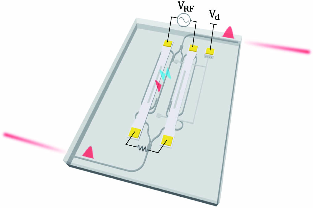
    Fig. 1. Schematic structure of the ML-MZM.
    (a) Operating principle of the proposed modulator; (b) cross section structure of the modulator arms.
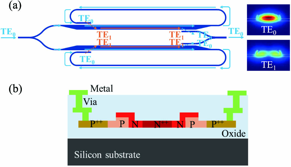
    Fig. 2. (a) Operating principle of the proposed modulator; (b) cross section structure of the modulator arms.
    (a) Top view of the designed ADC mode converter; (b) simulated electric field of ADC; (c) calculated CE and XT of the mode converter.
    Fig. 3. (a) Top view of the designed ADC mode converter; (b) simulated electric field of ADC; (c) calculated CE and XT of the mode converter.
    (a) Refractive index variations for TE0 and TE1 modes as a function of reverse bias for lateral PN junction. TE0 mode overlap with lateral PN junction of (b) single-mode waveguide and (c) two-mode waveguide. (d) Refractive index variations for TE0 and TE1 modes as a function of reverse bias for L-shaped PN junction. TE0 mode overlap with L-shaped PN junction of (e) single-mode waveguide and (f) two-mode waveguide.
    Fig. 4. (a) Refractive index variations for TE0 and TE1 modes as a function of reverse bias for lateral PN junction. TE0 mode overlap with lateral PN junction of (b) single-mode waveguide and (c) two-mode waveguide. (d) Refractive index variations for TE0 and TE1 modes as a function of reverse bias for L-shaped PN junction. TE0 mode overlap with L-shaped PN junction of (e) single-mode waveguide and (f) two-mode waveguide.
    Optical microscope image of (a) the fabricated ML-MZM, (b) the mode converter, (c) MMI.
    Fig. 5. Optical microscope image of (a) the fabricated ML-MZM, (b) the mode converter, (c) MMI.
    (a) Transmission spectra of the ML-MZM under different reverse voltages; (b) extracted phase change as a function of bias voltage.
    Fig. 6. (a) Transmission spectra of the ML-MZM under different reverse voltages; (b) extracted phase change as a function of bias voltage.
    (a) Microscope image of the ML-MZM with 1 mm phase shifter; (b) microscope image of the normal MZM with 2 mm phase shifter; (c) normal MZM transmission spectrum under various reverse voltages.
    Fig. 7. (a) Microscope image of the ML-MZM with 1 mm phase shifter; (b) microscope image of the normal MZM with 2 mm phase shifter; (c) normal MZM transmission spectrum under various reverse voltages.
    Measured EO-S21 response at −3 V bias voltage.
    Fig. 8. Measured EO-S21 response at 3  V bias voltage.
    (a) Schematic diagram of the high-speed measurement setup; (b) OOK eye diagram at 10 Gb/s; (c) OOK eye diagram at 15 Gb/s; (d) measured SNR response and bit allocation of 40 Gb/s DMT signal; (e) measured BER curve of 40 Gb/s DMT signal; (f) received constellations of four typical subcarriers of the DMT signal.
    Fig. 9. (a) Schematic diagram of the high-speed measurement setup; (b) OOK eye diagram at 10 Gb/s; (c) OOK eye diagram at 15 Gb/s; (d) measured SNR response and bit allocation of 40 Gb/s DMT signal; (e) measured BER curve of 40 Gb/s DMT signal; (f) received constellations of four typical subcarriers of the DMT signal.
    Optical modulation spectra of the modulator at different RF sinusoidal frequencies.
    Fig. 10. Optical modulation spectra of the modulator at different RF sinusoidal frequencies.
    Calculated EO response of ML-MZM with 1 and 0.5 mm phase shifter length.
    Fig. 11. Calculated EO response of ML-MZM with 1 and 0.5 mm phase shifter length.
    ReferenceStructureOperation BandBandwidth (GHz)VπL (V·cm)Speed (Gb/s)
    [11]MZMC-band14.70.5164
    [12]MZMO-band130.4624
    [13]MZMC-band2.60.6210
    [14]MZMC-band120.8110
    [16]MIMC-band120.8630
    [15]MIMC-band11.30.7240
    [17]MIMC-band120.9540
    This workML-MZMC-band50.3740
    Table 1. Performance Comparison of Carrier-Depletion-Based Silicon Interferometric Modulator
    Jiacheng Liu, Gangqiang Zhou, Jiangbing Du, Weihong Shen, Linjie Zhou, Zuyuan He. Silicon mode-loop Mach-Zehnder modulator with L-shaped PN junction for 0.37 V·cm VπL high-efficiency modulation[J]. Photonics Research, 2022, 10(1): 214
    Download Citation