
Yi-Lin YANG, Bo ZHANG, Dong-Feng JI, Yi-Wei WANG, Xiang-Yang ZHAO, Yong FAN. A wideband terahertz planar Schottky diode fourth-harmonic mixer with low LO power requirement[J]. Journal of Infrared and Millimeter Waves, 2020, 39(5): 540
- Journal of Infrared and Millimeter Waves
- Vol. 39, Issue 5, 540 (2020)
Abstract
Introduction
The unique characteristics of terahertz wave and its application in communication, imaging, and detection have attracted a lot of interests and researches[
Mixers using higher harmonics could be alternatives to solve the aforementioned problem[
In this paper, a 425 GHz fourth-harmonic mixer with wide operating band and low conversion loss is proposed. The mixer is designed with a combination of 3D EM simulation and harmonic balance simulation. An improved Hammerhead low pass filter, which has wide stopband and good rectangular coefficient[
1 Circuit Design
1.1 Configuration of the fourth-harmonic mixer
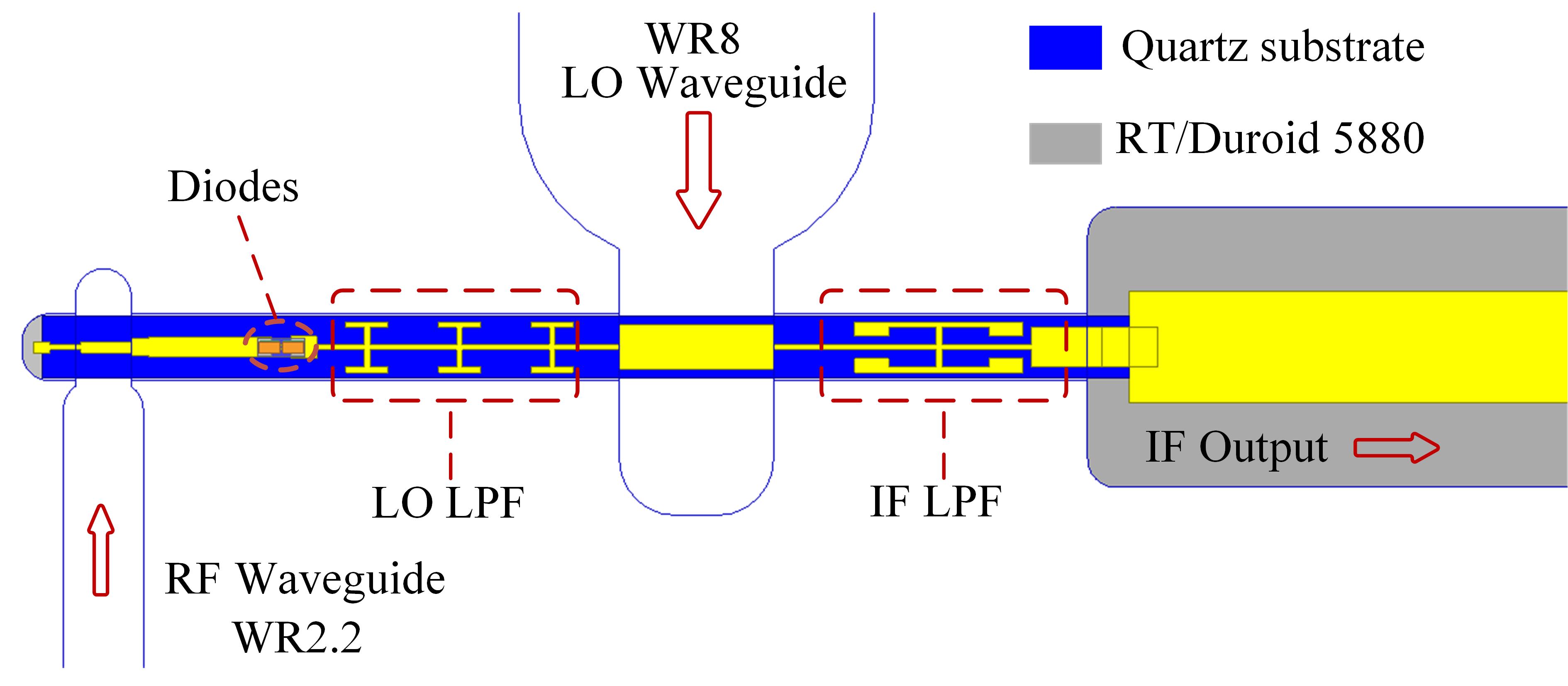
The configuration of the fourth-harmonic mixer circuit, shown in Fig. 1, includes an anti-paralleled of flip-chip Schottky diodes mounted on quartz-based microstrip circuit, RF and LO waveguide-to- microstrip transitions, intermediate-frequency (IF) and LO low-pass filters (LPF), as well as RF and LO matching networks. The dimensions of the suspended microstrip and the substrate are optimized to ensure that the RF and LO signals propagate on the quasi-TEM mode, and that no unwanted transmission mode coupling occurs[
![]()
Figure 1.Configuration of the proposed fourth-harmonic mixer
The suspended microstrip circuit is developed using quartz substrate with thickness of 50 μm, width of 220 μm and dielectric constant of 3.78. One end of suspended microstrip circuit is connected to a microstrip line based on Rogers 5880 substrate by bondwire or silver epoxy to output IF signal, so that a robust structure of the mixer can be obtained.
1.2 Modeling of the Schottky diode at THz band
For terahertz mixers, the Schottky diode is the key component to realize frequency conversion with its nonlinear characteristics. Higher operating frequency will limit the diode performances due to the parasitic effect. For millimeter wave and terahertz circuits, the influences brought by the diode parasitic will result in power loss and affect the input power coupling to the nonlinear diode junction, and the integral performances of the mixer circuit will be affected. Therefore, a modeling method combining the simulation of both electric field and circuit is essential to solve the problem.
The cross section view and parasitic parameters of the typical planar Schottky diode are shown in Fig. 2. The parasitic parameters will bring the degradation to the diode performance. The parasitic resistance, also called as series resistance RS, mainly consists of four parts: the epitaxial layer resistance Repi, the buffer region resistance Rbuffer, the ohmic contact resistance Rohmic, and the air bridge resistance Rfinger[
![]()
Figure 2.Cross section view and parasitic parameters of the planar Schottky diode
At submillimeter wave and terahertz bands, the parasitic effect of the planar Schottky diode cannot be ignored. Therefore, the model of the Schottky diode is built, as shown in Fig. 3. To design the mixer, the 3D EM simulations are used to obtain the S parameters of the chip package, which present the structure and parasitic effects of the diode. These S parameters are imported to the nonlinear circuit simulating software (Agilent’s ADS), while the external matching network of the fourth-harmonic mixer is optimized to realize the best performances.
![]()
Figure 3.(a) The 3D EM model of the planar Schottky diode (b) The picture of the Schottky diode applied manufactured by CETC-13
1.3 Methodology of reducing LO power for fourth-harmonic mixer based on optimized Schottky diodes
As mentioned above, the requirement of LO power is an important consideration among other performances. And the fourth-harmonic mixers need more LO power according to the previous researches. To analyze the relations between the parameters of the Schottky diode and the required LO power along with other performances, the equivalent circuit of the Schottky diode is built and shown in Fig. 4. The equivalent circuit is modeled with a junction resistor Rj (Vj), a junction capacitor Cj (Vj), and a series resistor RS (Vj).
![]()
Figure 4.(a) Simplified model of the diode junction (b) Equivalent circuit of the Schottky diode
From the equivalent circuit in Fig. 4, the relations between the junction resistance Rj, the junction capacitance Cj, and the series resistance RS can be obtained. The LO power dissipating on series resistance will be influenced by RS and Cj. With fixed diode voltage Vd between the anode and cathode, the bias voltage of the junction Vj increases with the decrease of RS and Cj, which is essential to reduce the LO power of mixers.
There are two ways to reduce the required LO power, either increasing the coupling efficiency between the source and the diode or reducing the power needed in the diode itself[
1. Minimize the parasitic elements as much as possible. The parasitic elements, especially the series resistance, contribute a lot to the dissipation of the LO power before it reaches the nonlinear junction resistance.
2. Reduce the junction capacitance adequately. Firstly, the junction capacitance contributes to the LO power dissipation. Apart from that, reducing the junction capacitance could increase the coupling efficiency between the external circuit and the diode itself according the previous researches[
3. Optimize the external matching network of the mixer diode. The losses of the external circuit and the matching network also greatly influence the LO power coupling to the diode junction.
Apart from the optimal LO power level, other performances of the Schottky diode and the fourth-harmonic mixer also need to be emphasized. For example, the reduction of the series resistance and junction capacitance could increase the cut off frequency.
The most important performances for the mixer are the conversion loss and noise temperature. Besides the matching circuit, parameters of the Schottky diodes also decide these performances. At terahertz band, the parasitic capacitances also contribute to the degradation of the noise and conversion loss and should be controlled as well[
Based on the analyses above, reducing the parasitic elements and decreasing junction capacitance of the Schottky diode adequately could reduce LO power and improve the integral performances. In this paper, the Schottky diodes applied for the fourth-harmonic mixers with low LO power requirement are designed with following steps.
1. Choose high doping density for epitaxial layer. According to the analyses, improving the doping density of the epitaxial layer is essential due to the importance to reduce the noise and series resistance. In this paper, the doping density of 5×1017 cm-3 is applied.
2. Optimize the structure of the Schottky diode. The thickness of the epitaxial layer needs to be reduced adequately to minimize the series while the parasitic capacitance can be reduced by decreasing pad area, increasing pad separation, decreasing substrate dielectric constant and substrate thickness. In Fig 5, the main dimensions of the applied Schottky diodes are illustrated. The thickness of the epitaxial layer is 0.2 μm, while the thickness of the buffer layer is 3 μm.
![]()
Figure 5.Dimensions of the Schottky diode applied in the proposed fourth-harmonic mixer
Due to the wet etching process, the angle between the GaAs substrate and the slanted side wall is 55⁰ [
Considering the fabrication processes of the mixer based on flip chip diodes, in which the diode chip is welded to the microstrip with silver epoxy, the pads of the Schottky diodes need to be large enough. In this design, the pad dimensions are 45 μm × 27 μm.
3. Decide the anode size. Based on the doping density and other parameters of the diode, the anode size should be optimized to realize good performances of the mixer, including low conversion loss and low optimal LO power. Reducing the size of the anode will lead to the decrease of the junction capacitance but will also increase the series resistance. The simulation of the ideal fourth-harmonic mixer is developed using ideal diodes without considering the diode packages. The conversion loss and optimum LO power with different zero junction capacitance (Cj0) of the mixer diode are shown in Fig. 6. Best performances are achieved with Cj0 around 1 fF. Based on other parameters of the diodes, an optimum anode diameter of 0.7 μm with corresponding Cj0 of 1.1 fF is obtained.
![]()
Figure 6.(a) Optimum conversion loss of the mixer with different
The Schottky diodes specially designed for the fourth-harmonic mixer in this paper are manufactured by CETC-13. Its overall dimensions are 160 μm × 50 μm × 30 μm. The mixer diodes are with following parameters: saturation current Isat = 35 fA, series resistance RS= 20Ω, ideality factor η = 1.3, zero voltage junction capacitance Cj0 = 1.1 fF, and built-in potential Vbi = 0.73 V.
Based on the specialized Schottky diodes, the matching network of the fourth-harmonic mixer is further optimized in ADS with S parameters of each part of the mixer, and the final performances of the fourth-harmonic mixer could be obtained with harmonic balance simulation in ADS.
1.4 Wide stopband terahertz low pass filter using hammerhead configuration
The main function of the LO low-pass filter (LPF) is to isolate the RF signal and the unused harmonics from the LO port, while directing the LO signal towards the diodes with lower loss. In this paper, the LPF uses the hammerhead configuration, which is more compact compared with a stepped- impedance LPF with same passband and stopband. The comparison between the proposed hammerhead LPF and a stepped-impedance LPF with similar passband is shown in Fig. 7. Simulated results show that insertion loss of the proposed Hammerhead LPF is higher than 20 dB from 182 to 500 GHz, which validates the good isolation for RF signal (325 ~ 400 GHz) and unused harmonic signals generated at the mixer diodes (second harmonic signal with frequency from 162 GHz to 250 GHz). The insertion loss of the LO filter is lower than 0.4 dB from DC to 130 GHz, which enables the IF and LO signal passing with low loss. Compared with the stepped-impedance LPF with similar passband, the proposed hammerhead LPF exhibits much wider stopband and more compact size. The good performances of the LO filter also contribute to the reduction of LO power.
![]()
Figure 7.(a) Topology and simulation results of the wide stopband and high rejection LO low pass filter
1.5 Overall circuit simulation
The overall simulation of the fourth-harmonic mixer is developed with a combination of 3D electromagnetic (EM) simulations and harmonic balance simulation. The 3D EM simulations of the different parts of the mixer circuit including the RF and LO waveguide-to-microstrip transitions, diode cells, low-pass filters were developed separately using High Frequency Software Simulator (HFSS) and exported as S-parameter Touchstone files into ADS. The simulated performances with different LO power are shown in Fig. 8. Simulated results show that, the best performances are obtained with an optimal LO power of 7 mW. The single sideband (SSB) conversion loss is better than 20 dB from 325 to 500 GHz with fixed IF frequency of 1 GHz and the simulated noise temperature is 3 060~12 800 K within this frequency band.
![]()
Figure 8.Simulated performances of the proposed fourth-harmonic mixer with different LO power (a) SSB conversion loss, (a) DSB noise temperature
2 Measurement results and analysis
The Schottky diodes specially designed for the proposed fourth-harmonic mixer were manufactured in CETC-13 and the mixer circuit was fabricated and measured in UESTC. The mixer circuit mounting in the split block is shown in Fig. 9. It’s manufactured using 50 μm-thick quartz substrate, while the anti-paralleled Schottky diodes were welded to the circuit with silver epoxy. The overall dimensions of the quartz substrate are 3.5 mm × 0.22 mm × 0.05 mm. The whole circuit is suspended in an enclosed channel crossing the RF and LO waveguides, which are WR2.2 (0.508 mm × 0.254 mm) and WR8 (2.032 mm × 1.016 mm), respectively.
![]()
Figure 9.Inside photograph of the fourth-harmonic mixer
The test setup for SSB conversion loss is shown in Fig. 10. The RF signal was provided with a ×12 multiplier chain and the power of RF signal should be controlled at a low level (0.1 mW in this paper) to ensure the mixer working in its linear range. Meanwhile, the LO signal was generated by a ×6 multiplier chain with operating frequency from 81 to 125 GHz. As for the measurement for noise temperature of the fourth-harmonic mixer, the Y factor method and gain procedure illustrated in Ref.[31] are applied. The test setup for noise temperature is shown in Fig. 11.
![]()
Figure 10.Test setup for conversion loss of the fourth-harmonic mixer
![]()
Figure 11.Test setup for noise temperature of the fourth-harmonic mixer
According to the measured results, the best performances of the fourth-harmonic mixer are achieved with LO power of 7 mW. Fig. 12 shows the comparison between the simulated and measured performances with LO power of 7 mW and fixed IF frequency of 1 GHz. The SSB conversion loss of the fourth-harmonic mixer is 14.2 ~ 20 dB within the frequency band from 340 to 490 GHz, while the noise temperature is 4020 ~ 17100 K in this frequency range. The best performances of the mixer are realized when the RF is 418 GHz, with conversion loss of 14.2 dB and noise temperature of 4020 K. Good agreements are achieved between the simulated and measured results. The slight difference is brought by inconsistency between the calculated parameters applied in simulation (such as series resistances, junction capacitance) and the actual ones. Inaccurate assembly process could also lead to the differences between the simulated and measured results.
![]()
Figure 12.Comparison between simulated conversion loss and measured results of the proposed mixer with fixed IF frequency of 1 GHz and optimum LO power of 7 mW
The comparisons between the performances of the proposed and previously reported fourth-harmonic mixers considering both conversion loss and optimal LO power are shown in Table I. It can be concluded that the proposed mixer achieves better conversion loss over a wide frequency band with lower LO pump power. In this paper, the fourth-harmonic mixer is developed based on the optimized Schottky diodes and the best LO power is lower compared with that in Ref.[18-19]. High doping density is applied and several parameters of the Schottky diodes, such as anode size, are optimized to realize low optimal LO power. The performances of the mixer have validated the proposed methods to design the mixer with low LO power requirement.
| Ref. | RF freq. /GHz | CL /dB | NT (DSB) /K | OLOP /mW |
|---|---|---|---|---|
| [ | 600 | 27 (SSB) | NI | 20 |
| [ | 430 ~ 480 | 14 ~ 20 (DSB) | 7900 ~ 20000 | 10 |
| [ | 325~ 500 | 15 ~ 22 (SSB) | NI | 20 |
Table 1. Summary of the performances of the reported fourth-harmonic mixer
Schottky diodes with small anode size and highly doped epitaxial layer are utilized to realize the good performances of terahertz mixers. These characteristics lead to the low power capacity of the mixer diodes. Therefore, mixers using high harmonics are usually restricted by high optimal LO power, which could damage the diodes. The method of reducing LO power proposed in this paper can resolve the conflict between the need of excessive LO power for high harmonic terahertz mixers and the low power capacity of the mixer diode. It will contribute to the development of terahertz systems using high harmonic mixers in the future.
3 Conclusion
This paper presents the development of a terahertz fourth-harmonic mixer with wide operating band, low conversion loss and low LO power requirement. The 3D model of the flip chip Schottky diode was built and a combination of EM simulation and nonlinear harmonic balanced simulation were applied to design the mixer. Meanwhile, the methods of realizing high harmonic mixer with good performances and less LO power are introduced. With optimum LO power of 7 mW, the measured conversion loss of the proposed fourth-harmonic mixer is 14.2 ~ 20 dB from 340 to 490 GHz, while the measured noise temperature is 4 020~17 100 K in this frequency range. The fourth-harmonic mixer proposed in this paper features lower LO power requirement compared with previous research. It can be applied in terahertz systems to simplify the system with lower LO frequency. The methods of reducing the required LO power can be utilized to improve the performances of mixers using even higher harmonics in the future.
References
[1] I Hosako, N Sekine, M Patrashin et al. At the dawn of a new era in terahertz technology. Proceedings of the IEEE, 95, 1611-1623(2007).
[2] P H Siegel. THz instruments for space. IEEE Transactions on Antennas and Propagation, 55, 2957-2965(2007).
[3] T Kleine-Ostmann, T Nagatsuma. A review on terahertz communications research. Terahertz Waves, 32, 143-171(2011).
[4] Z Chen, B Zhang, Y Zhang et al. 220 GHz outdoor wireless communication system based on a Schottky-diode transceiver. IEICE Electronics Express, 13, 20160282-20160282(2016).
[5] E Schlecht, J Gill, R Dengler et al. A unique 520–590 GHz biased subharmonically-pumped Schottky mixer. IEEE Microwave and Wireless Components Letters, 17, 879-881(2007).
[6] P J Sobis, N Wadefalk, A Emrich et al. A broadband, low noise, integrated 340 GHz Schottky diode receiver. IEEE Microwave and Wireless Components Letters, 22, 366-368(2012).
[7] J L Hesler, W R Hall, T W Crowe et al. Fixed-tuned submillimeter wavelength waveguide mixers using planar Schottky-barrier diodes. IEEE transactions on microwave theory and techniques, 45, 653-658(1997).
[8] E Schlecht, J V Siles, C Lee et al. Schottky diode based 1.2 THz receivers operating at room-temperature and below for planetary atmospheric sounding. IEEE Transactions on Terahertz Science and Technology, 4, 661-669(2014).
[9] B Zhang, Y Fan, Z Chen et al. An improved 110–130-GHZ fix-tuned subharmonic mixer with compact microstrip resonant cell structure. Journal of Electromagnetic Waves and Applications, 25, 411-420(2011).
[10] Z Chen, B Zhang, Y Fan et al. Design of a low noise 190–240 GHz subharmonic mixer based on 3D geometric modeling of Schottky diodes and CAD load-pull techniques. IEICE Electronics Express, 13, 20160604-20160604(2016).
[11] G Liu, B Zhang, L Zhang et al. 420GHz subharmonic mixer based on heterogeneous integrated Schottky diode. IEICE Electronics Express, 14, 20170459(2017).
[12] B T Bulcha, J L Hesler, V Drakinskiy et al. 9-3.2 THz Schottky based harmonic mixer design and characterization[C].
[13] D Ji, B Zhang, Y Yang et al. A 220-GHz Third-Harmonic Mixer Based on Balanced Structure and Hybrid Transmission Line. IEEE Access, 7, 50007-50011(2019).
[14] B Zhang, X Lv, J He et al. 1.1 THz tenth harmonic mixer based on planar GaAs Schottky diode. Antennas & Propagation(2019).
[15] Z Liu, R M Weikle. High-order subharmonically pumped mixers using phased local oscillators. IEEE transactions on microwave theory and techniques, 54, 2977-2982(2006).
[16] J Schur, M Ruf, L P Schmidt. Design of a 4 th harmonic Schottky diode mixer for THz frequencies, 756-757(2007).
[17] J Schur, M Ruf, L P Schmidt. A 4 th harmonic schottky diode mixer-facilitated access to THz frequencies. CA, 1-2(2008).
[18] I Maestrojuan, I Ederra, R Gonzalo. Fourth-harmonic Schottky diode mixer development at sub-millimeter frequencies. IEEE Transactions on Terahertz Science and Technology, 5, 518-520(2015).
[19] J Deng, Q Lu, D Jia et al. Wideband fourth-harmonic mixer operated at 325–500 GHz. IEEE Microwave and Wireless Components Letters, 28, 242-244(2018).
[20] J M Pérez-Escudero, C Quemada, R Gonzalo et al. Comparison of Fourth-harmonic and Combined Doubler/Subharmonic Mixer with integrated MMIC based Local Oscillator. France, 1-2(2019).
[21] C Wang, Y He, B Lu et al. Robust sub-harmonic mixer at 340 ghz using intrinsic resonances of hammer-head filter and improved diode model. Terahertz Waves, 38, 1397-1415(2017).
[22] F Zhong, B Zhang, Y Fan et al. Application of Implicit Space Mapping in the Design of Hammerhead Filter in Millimeter-Wave Band. Engineering and Technology, 4, 670-674(2012).
[23] J Jun, H E Yue, W Cheng et al. 0.67 THz sub-harmonic mixer based on Schottky diode and hammer-head filter. Journal of infrared and millimeter waves, 35, 418-424(2016).
[24] J Treuttel, L Gatilova, A Maestrini et al. A 520–620-GHz Schottky receiver front-end for planetary science and remote sensing with 1070 K–1500 K DSB noise temperature at room temperature. IEEE transactions on terahertz science and technology, 6, 148-155(2015).
[25] A Y Tang, J Stake. Impact of eddy currents and crowding effects on high-frequency losses in planar Schottky diodes. IEEE Transactions on Electron Devices, 58, 3260-3269(2011).
[26] T W Crowe, W C B Peatman, W L Bishop. GaAs Schottky barrier diodes for space based applications at submillimeter wavelengths, 256-272(1990).
[27] I Mehdi, P H Siegel. Effect of parasitic capacitance on the performance of planar subharmonically pumped Schottky diode mixers. Michigan, 379-393(1994).
[28] T W Crowe, R J Mattauch, H P Roser et al. GaAs Schottky diodes for THz mixing applications. Proceedings of the IEEE, 80, 1827-1841(1992).
[29] T W Crowe, R J Mattauch. Analysis and optimization of millimeter-and submillimeter- wavelength mixer diodes. IEEE transactions on microwave theory and techniques, 35, 159-168(1987).
[30] S Iida. Ito K., Selective etching of gallium arsenide crystals in H2SO4-H2O2-H2O system. Journal of The Electrochemical Society, 118, 768-771(1971).
[31] I Maestrojuan, S Rea, I Ederra et al. Experimental analysis of different measurement techniques for characterization of millimeter‐ wave mixers. Microwave and Optical Technology Letters, 56, 1441-1447(2014).

Set citation alerts for the article
Please enter your email address
© Copyright 2018-2021 | Chinese Laser Press. All Rights Reserved 沪ICP备15018463号-20