• Laser & Optoelectronics Progress
  • Vol. 58, Issue 17, 1712001 (2021)
Tao Xiong1, Shuanggao Li1、*, Qi Li1, and Ziyue Zhao2
Author Affiliations
  • 1College of Mechanical and Electrical Engineering, Nanjing University of Aeronautics & Astronautics, Nanjing , Jiangsu 210016, China
  • 2AVIC Beijing Changcheng Institute of Metrology & Measurement, Beijing 100095, China
  • show less
    DOI: 10.3788/LOP202158.1712001 Cite this Article Set citation alerts
    Tao Xiong, Shuanggao Li, Qi Li, Ziyue Zhao. Station Planning of Laser Tracker Based on Combination Measurement[J]. Laser & Optoelectronics Progress, 2021, 58(17): 1712001 Copy Citation Text show less
    Combination measurement constraint model
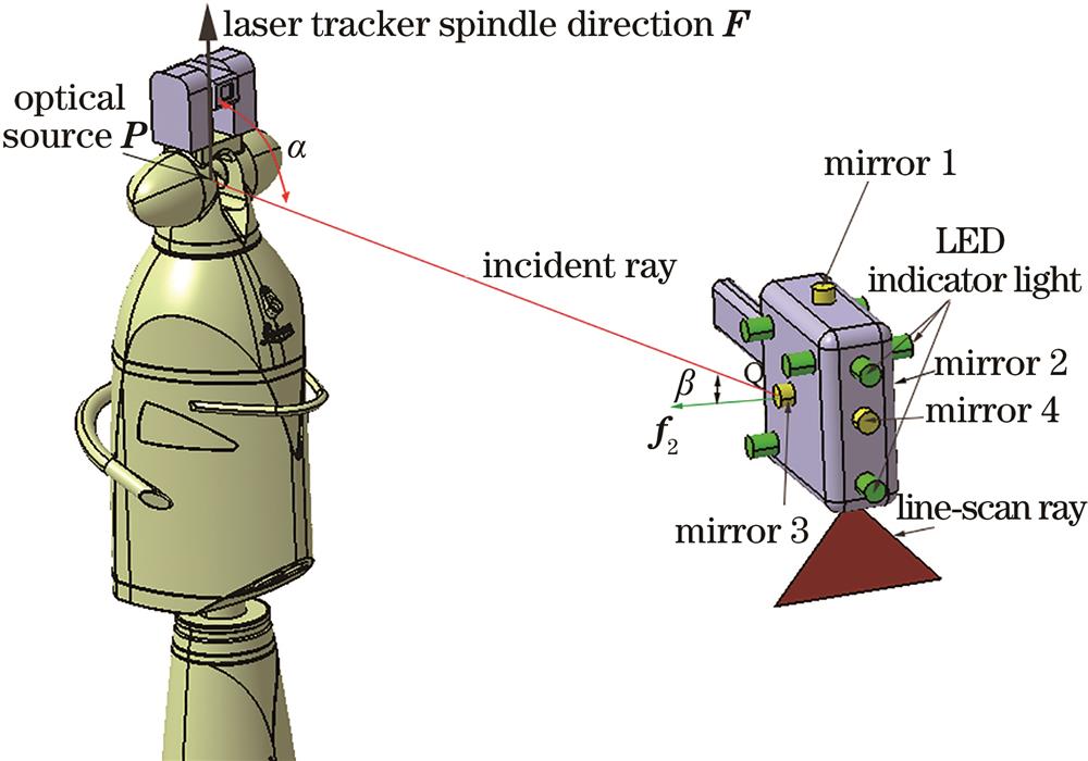
    Fig. 1. Combination measurement constraint model
    Idea of station planning and mirror replacement
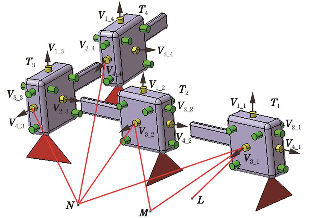
    Fig. 2. Idea of station planning and mirror replacement
    Flow of station planning method
    Fig. 3. Flow of station planning method
    Experiment device and platform
    Fig. 4. Experiment device and platform
    Simulation software interface and display window
    Fig. 5. Simulation software interface and display window
    Scanning path
    Fig. 6. Scanning path
    Station setting by the empirical method. (a) The 28th T-Scan pose; (b) the 45th T-Scan pose; (c) the 73rd T-Scan pose
    Fig. 7. Station setting by the empirical method. (a) The 28th T-Scan pose; (b) the 45th T-Scan pose; (c) the 73rd T-Scan pose
    Simulated picture and actual measurement picture of the 3rd planning result. (a) Simulated picture;(b) actual measurement picture
    Fig. 8. Simulated picture and actual measurement picture of the 3rd planning result. (a) Simulated picture;(b) actual measurement picture
    Simulated picture and actual measurement picture of the 4th planning result. (a) Simulated picture; (b) actual measurement picture
    Fig. 9. Simulated picture and actual measurement picture of the 4th planning result. (a) Simulated picture; (b) actual measurement picture
    OrderScanning parameter valueScanning pose pointPose of mirror 1Pose of mirror 2Pose of mirror 3Pose of mirror 4
    1x1,y1,z1,θx1,θy1,θz1T1V1_1V2_1V3_1V4_1
    ixi,yi,zi,θxi,θyi,θziTiV1_iV2_iV3_iV4_i
    nxn,yn,zn,θxn,θyn,θznTnV1_nV2_nV3_nV4_n
    Table 1. Scanning path pose points and mirror poses
    Order of TiT-Scan mirror numberLaser tracker light source position coordinateLaser tracker spindle direction
    1 to 164(2000,-1000,1110)(0,0,1)
    17 to 282
    29 to 443(0,-4000,1110)(0,0,1)
    45 to 564
    57 to 582(1000,-4000,1110)(0,0,1)
    59 to 604
    61 to 622
    63 to 644
    65 to 662
    67 to 684
    69 to 702
    71 to 734
    Table 2. Station results by empirical method
    Order of TiT-Scan mirror numberLaser tracker light source position coordinateLaser tracker spindle direction
    1 to 163(-1365.240642,-4475.935829,1110)(0,0,1)
    17 to 284
    29 to 443
    45 to 584
    59 to 603
    61 to 624
    63 to 643
    65 to 664
    67 to 683
    69 to 704
    71 to 733
    Table 3. The 3rd planning result
    Order of TiT-Scan mirror numberLaser tracker light source position coordinateLaser tracker spindle direction
    1 to 164(3164.683301,-2887.332054,1110)(0,0,1)
    17 to 282
    29 to 444
    45 to 582
    59 to 604
    61 to 622
    63 to 644
    65 to 662
    67 to 684
    69 to 702
    71 to 734
    Table 4. The 4th planning result
    Tao Xiong, Shuanggao Li, Qi Li, Ziyue Zhao. Station Planning of Laser Tracker Based on Combination Measurement[J]. Laser & Optoelectronics Progress, 2021, 58(17): 1712001
    Download Citation