• High Power Laser Science and Engineering
  • Vol. 9, Issue 2, 02000e28 (2021)
Xiaomei Zhang1、2、3, Baifei Shen2、*, Lingang Zhang1、3, and Yin Shi
Author Affiliations
  • 1State Key Laboratory of High Field Laser Physics, Shanghai Institute of Optics and Fine Mechanics, Chinese Academy of Sciences, Shanghai, China
  • 2Department of Physics, Shanghai Normal University, Shanghai, China
  • 3CAS Center for Excellence in Ultra-intense Laser Science, Shanghai, China
  • show less
    DOI: 10.1017/hpl.2021.14 Cite this Article Set citation alerts
    Xiaomei Zhang, Baifei Shen, Lingang Zhang, Yin Shi. New phase-matching selection rule to generate angularly isolated harmonics[J]. High Power Laser Science and Engineering, 2021, 9(2): 02000e28 Copy Citation Text show less
    Schematic of the chain selection rule for the proposed approach. Two laser pulses a1(ω) and a2(ω), irradiate a thin foil symmetrically at a large crossing angle 2θ, considering the normal direction of the target surface. High-order harmonics are emitted at different spatial locations at an angle α, which is determined by the conservation of energy and linear momentum through the chain selection rule. This chain selection rule is demonstrated by the phase-matching schemes (a) and (b).
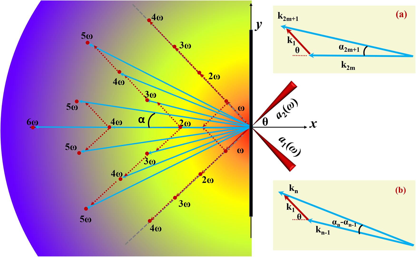
    Fig. 1. Schematic of the chain selection rule for the proposed approach. Two laser pulses a1(ω) and a2(ω), irradiate a thin foil symmetrically at a large crossing angle 2θ, considering the normal direction of the target surface. High-order harmonics are emitted at different spatial locations at an angle α, which is determined by the conservation of energy and linear momentum through the chain selection rule. This chain selection rule is demonstrated by the phase-matching schemes (a) and (b).
    (a) Configuration of the PIC simulation box. The input laser field distribution before the lasers strike the target. (b) Electric field (Ez) distribution of the harmonics for two counter-rotation CP lasers after the lasers are reflected completely from the target, where the fundamental components are filtered out. The dashes denote the location of the target. The field is normalized to (3.2×10¹² V/m).
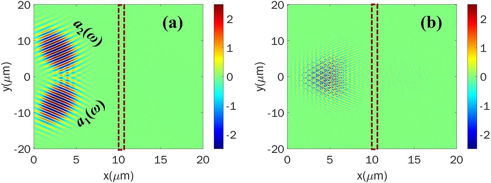
    Fig. 2. (a) Configuration of the PIC simulation box. The input laser field distribution before the lasers strike the target. (b) Electric field (Ez) distribution of the harmonics for two counter-rotation CP lasers after the lasers are reflected completely from the target, where the fundamental components are filtered out. The dashes denote the location of the target. The field is normalized to (3.2×10¹² V/m).
    The spectrum distribution of harmonics in k-space corresponding to that in Figure 2(b). Here 2ω11 is the second harmonic in the direction normal to the target; 3ω30, 3ω21, 3ω12, and 3ω03 are the third harmonics emitted in different directions; 4ω40, 4ω31, 4ω22, 4ω13, and 4ω04 are the fourth harmonics emitted in different directions; and 5ω32 and 5ω23 are the fifth harmonics emitted in different directions. The small white circles indicate the harmonics derived from the new phase matching selection rule Equation (4). The blue dashed lines indicate that same order harmonics in different directions have the same wavenumber.
    Fig. 3. The spectrum distribution of harmonics in k-space corresponding to that in Figure 2(b). Here 2ω11 is the second harmonic in the direction normal to the target; 3ω30, 3ω21, 3ω12, and 3ω03 are the third harmonics emitted in different directions; 4ω40, 4ω31, 4ω22, 4ω13, and 4ω04 are the fourth harmonics emitted in different directions; and 5ω32 and 5ω23 are the fifth harmonics emitted in different directions. The small white circles indicate the harmonics derived from the new phase matching selection rule Equation (4). The blue dashed lines indicate that same order harmonics in different directions have the same wavenumber.
    Electric field (Ez) distributions of the (a), (d) second harmonic (2ω11), (b), (e) third harmonic (3ω21), and (c), (f) fourth harmonic (4ω31) in the (a)–(c) x–y plane at z = 0, and (d)–(f) are the section planes taken along the black dashed lines in (a)–(c).
    Fig. 4. Electric field (Ez) distributions of the (a), (d) second harmonic (2ω11), (b), (e) third harmonic (3ω21), and (c), (f) fourth harmonic (4ω31) in the (a)–(c) xy plane at z = 0, and (d)–(f) are the section planes taken along the black dashed lines in (a)–(c).
    (a) Energy conversion efficiency for the harmonics in the reflected directions. (b) Energy conversion efficiency for the harmonics of the same order emitted at different angles.
    Fig. 5. (a) Energy conversion efficiency for the harmonics in the reflected directions. (b) Energy conversion efficiency for the harmonics of the same order emitted at different angles.
    The spectrum distribution of harmonics in k-space after the lasers are reflected completely from the target, where the fundamental components are filtered out in the cases of (a) a0 =10, (b) a0=20, and (c) a0=50.
    Fig. 6. The spectrum distribution of harmonics in k-space after the lasers are reflected completely from the target, where the fundamental components are filtered out in the cases of (a) a0 =10, (b) a0=20, and (c) a0=50.
    Xiaomei Zhang, Baifei Shen, Lingang Zhang, Yin Shi. New phase-matching selection rule to generate angularly isolated harmonics[J]. High Power Laser Science and Engineering, 2021, 9(2): 02000e28
    Download Citation