
Jingwen Dong, Qiang Sun, Zekun Jiao, Liqi Zhang, Ziqiang Yin, Jiajie Huang, Jinghan Yu, Shu Wang, Shangyuan Li, Xiaoping Zheng, Wangzhe Li, "Photonics-enabled distributed MIMO radar for high-resolution 3D imaging," Photonics Res. 10, 1679 (2022)
- Photonics Research
- Vol. 10, Issue 7, 1679 (2022)
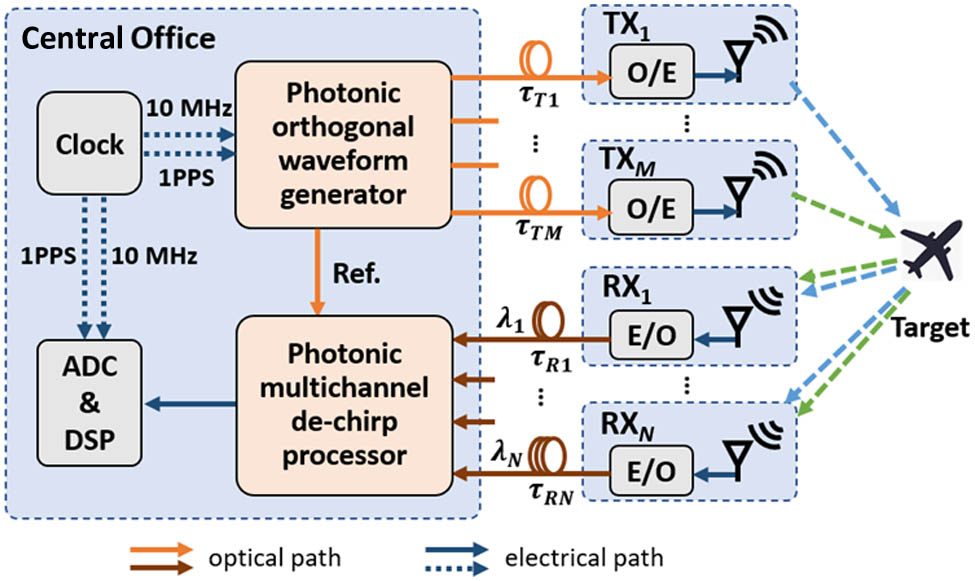
Fig. 1. Architecture of the proposed photonics-enabled distributed MIMO radar. E/O, electro-optical converter; O/E, opto-electrical converter; ADC, analog-to-digital converter; DSP, digital signal processor; Ref., reference signal.
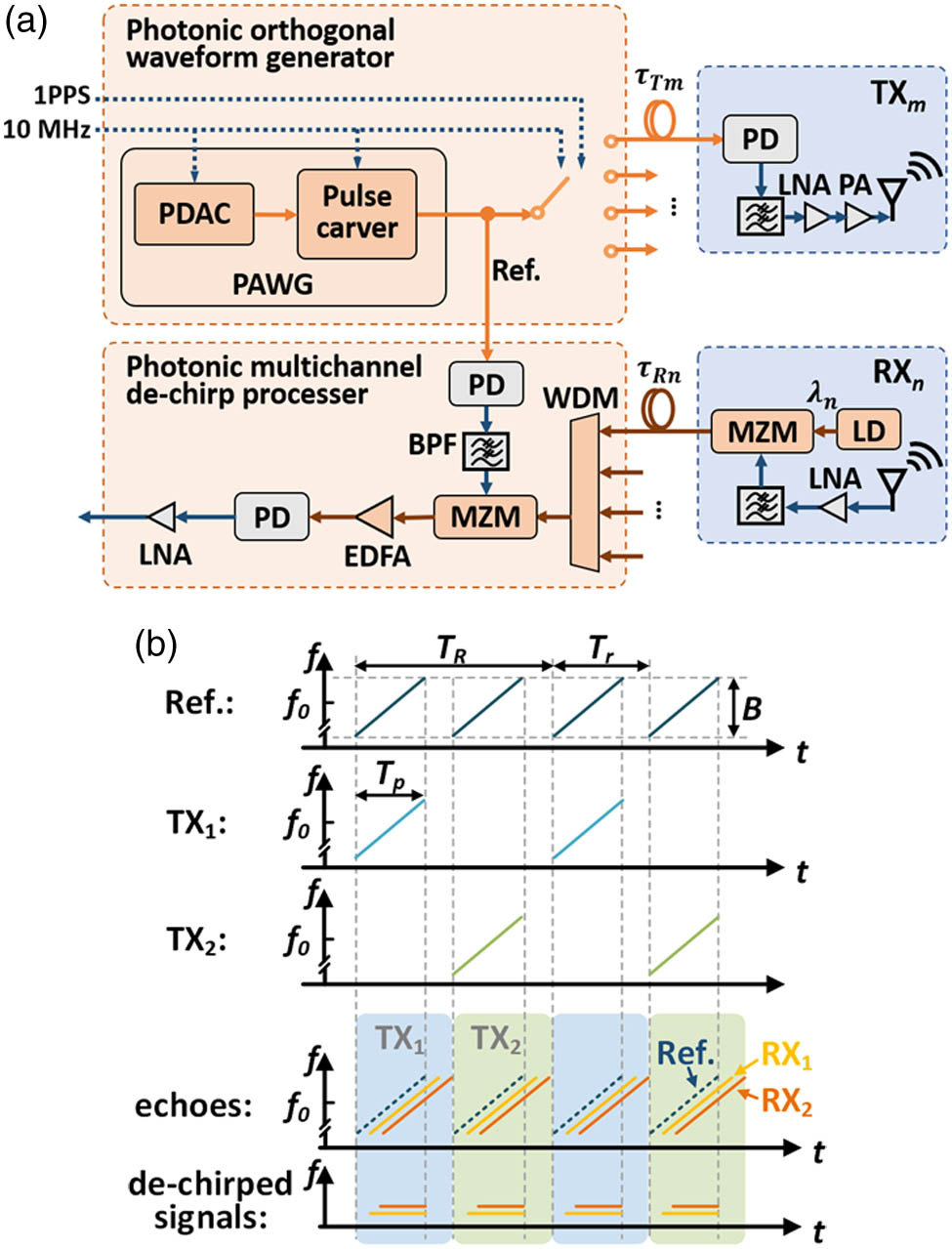
Fig. 2. (a) Schematic diagram of the proposed photonics-enabled distributed MIMO radar. (b) Instantaneous frequency–time diagram of the reference signal, echoes, and de-chirped signals, in the case of a 2 × 2 f 0 B T p T r T R
Fig. 3. Flowchart of 3D imaging based on the proposed system.
Fig. 4. Test results of a static TCR. (a) Spectrum of one period de-chirped signal relative to one TX and four RXs. (b) Phase drift of RX 1 RX 1 RX 4
Fig. 5. Test results of a pair of rotating TCRs. (a) Single-channel ISAR image. (b) Range slice of one TCR.
Fig. 6. (a) Overhead topology of distributed MIMO radar on a bridge and the flight path passing by. (b) Photograph of distributed MIMO radar, including a CO, four TXs, and four RXs. (c) Layout of distributed MIMO radar and corresponding APCs.
Fig. 7. Photograph and single-channel ISAR image of the imaged airplane.
Fig. 8. Comparison of reconstructed 3D images obtained by conventional MIMO radar and established MIMO radar: (a) the former including two TXs and four RXs with a maximum baseline of 1.3 m [28]; (b) the latter including two TXs and four RXs with a maximum baseline of 4.2 m; (c) the latter including four TXs and four RXs with a maximum baseline of 9 m.
|
Table 1. Main Design Parameters of the Established System


Set citation alerts for the article
Please enter your email address

© Copyright 2018-2021 | Chinese Laser Press. All Rights Reserved 沪ICP备15018463号-20