
Jingwen Dong, Qiang Sun, Zekun Jiao, Liqi Zhang, Ziqiang Yin, Jiajie Huang, Jinghan Yu, Shu Wang, Shangyuan Li, Xiaoping Zheng, Wangzhe Li, "Photonics-enabled distributed MIMO radar for high-resolution 3D imaging," Photonics Res. 10, 1679 (2022)
- Photonics Research
- Vol. 10, Issue 7, 1679 (2022)
Abstract
1. INTRODUCTION
Three-dimensional (3D) imaging radar is considered as an essential sensor for all-time and all-weather space surveillance, surveying and mapping, target classification and identification, etc. Compared with traditional two-dimensional (2D) imaging radar, such as inverse synthetic aperture radar (ISAR), it can provide more geometric features and better visualization through 3D energy distribution of scatterers [1–6]. To achieve high resolution in three dimensions, both a broad operating band and a large aperture are required, corresponding to range and angular resolutions, respectively, and the latter is commonly realized by a sparsely distributed antenna array. However, with an ever-increasing demand on 3D resolution, conventional radar arrays based on pure electronics have been encountering significant challenges: (1) the bandwidth of radar signal generation, distribution, reception, and processing is severely limited; (2) coaxial transmission loss becomes unbearable as array coverage enlarges; (3) coherence among widely separated array nodes is hardly guaranteed under the synchronization errors relying on the Global Navigation Satellite System (GNSS) or other wireless methods; (4) system cost and complexity inevitably increase with more array nodes needed due to aperture size requirement and sparsity constraint [7,8]. To resolve these issues, fast growing technologies based on the cross-fertilization between microwave photonics and radar arrays provide promising solutions [9–17]. The intrinsic ultra-wide bandwidth of photonics has been deeply applied in radar imaging and extensively validated to improve range resolution. Moreover, by virtue of multi-dimensional multiplexing, low-loss and high-capacity transmission, and phase-stable distribution, microwave photonics would enable centralized architecture via highly coherent fusion of multi-node signals as well as a large-scale array with much simpler implementations. These specialties permit a larger equivalent aperture and wider observation angle, leading to improved angular resolution and superior spatial diversity.
Recently, researches on photonics-enabled radar array have been intensively conducted [18–25]. In Ref. [19], a collocated multiple-input and multiple-output (MIMO) radar is demonstrated. Based on orthogonal frequency-division multiplexing (OFDM) transmitting and wavelength-division multiplexing receiving, a linear equivalent aperture is formed by just a few transceivers to achieve high azimuth resolution. In Ref. [21], another MIMO radar is established in a real port for 2D maritime surveillance. Benefitting from the high signal stability among a deployed distributed fiber-optic network, both spatial resolution and monitoring capabilities are evaluated to be enhanced. In Ref. [23], a further expanded radar array up to 12 km is reported, which employs a fiber-based time–frequency synchronization network for full coherent detection. High resolution and high signal-to-noise ratio (SNR) are simultaneously realized in 2D imaging in the laboratory. Additionally, 3D imaging in near and far fields is experimentally demonstrated, in which a photonics-enabled 2D aperture is constructed to obtain scattering characteristics in azimuth and elevation directions [24,25]. All these researches show the great potential of photonics to bring unprecedented imaging performance, due to its possibilities of centralized processing and coherent fusion of multi-channel signals. On the other hand, in effectuating these possibilities, multiple reference signal matching with different channels should be independently generated in a central office (CO) and transferred to corresponding receivers (RXs) for separate processing, whether de-chirping or downconverting. Even in some distributed systems, accessional synchronizing signals, such as time and frequency signals or gate signals, are inescapably delivered to remote stations. Considering that more channels are needed for a larger aperture and high angular resolution under unambiguous and sparsity requirements, the above operations undoubtedly intensify the contradiction between system complexity and resolution.
To overcome such a dilemma, a photonics-enabled distributed MIMO radar for high-resolution 3D imaging is proposed based on the following two steps. First, a novel centralized architecture is designed based on the conjunctive multiplexing of time, frequency, and wavelength divisions. Both generation of multi-channel orthogonal signals and de-chirping reception of reflected echoes are implemented on a common reference signal in the CO. Thus, the photonic signals are transmitted over fibers, and the only task for transceivers is the signal conversion between photonics and electronics. In this way, structures of the remote station and the CO are simplified while maintaining high inter-channel coherence and low transmission loss for a long baseline. Second, with the efficient combination of compressed sensing (CS)-based super-resolution algorithms and traditional ISAR imaging methods, a sparse array and a synthetic aperture are jointly utilized to reduce the number of required transceivers, which further alleviates the aforementioned contradiction. X-band
Sign up for Photonics Research TOC. Get the latest issue of Photonics Research delivered right to you!Sign up now
2. PRINCIPLE
A. System Architecture
Figure 1 shows the architecture of the proposed photonics-enabled distributed MIMO radar, including a CO, multiple transmitters (TXs, denoted by
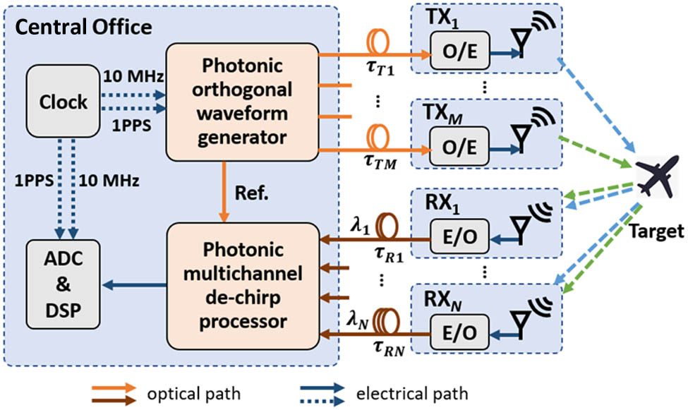
Figure 1.Architecture of the proposed photonics-enabled distributed MIMO radar. E/O, electro-optical converter; O/E, opto-electrical converter; ADC, analog-to-digital converter; DSP, digital signal processor; Ref., reference signal.
A detailed scheme of the proposed radar is depicted in Fig. 2(a). For clarity, the instantaneous frequency–time relationships of different signals, under the circumstance of a
![]()
Figure 2.(a) Schematic diagram of the proposed photonics-enabled distributed MIMO radar. (b) Instantaneous frequency–time diagram of the reference signal, echoes, and de-chirped signals, in the case of a
At the TX, the transferred optical signal is converted into an RF signal, which subsequently passes through a BPF and several stages of amplifiers for emission. In this way, in far-field conditions where the distances from different antennas to the same target are similar, echoes received by the RX from all TXs are orthogonal and detachable in time domain if the lengths/delays of the connected fibers are not too different. For simplicity and without loss of generality, the following theoretical analysis is conducted in the case of a single TX.
At
The generated photonic echoes from all RXs are then transferred back to the CO through different path delays and combined in a wavelength division multiplexer. The output signal can be given as
By means of multi-dimensional multiplexing, including time, wavelength, and de-chirp frequency, multi-channel signal generation and echo reception are completed sharing a common reference signal, resulting in a centralized MIMO architecture with high coherence within the fiber network.
Note that during fiber link designing, to avoid spectrum conflict, the de-chirped frequencies of all channels should not be overlapped. Specifically, in the above far-field conditions, for a given interesting scope corresponding to the range of travel time
B. 3D Imaging Method
The broadband operation of the above system ensures high range resolution. For high angular resolutions in the other two directions, a large 2D aperture is essential. To minimize the number of required transceivers, a super-resolution reconstruction algorithm and the conventional ISAR imaging method are efficiently combined, which are, respectively, based on a sparse array and a synthetic aperture, providing an optimal solution to the trade-off between resolution and complexity [28].
The target is assumed to move at a constant velocity
A flowchart of the 3D imaging process is shown in Fig. 3. First, a range profile of the target is reconstructed via fast Fourier transform (FFT) of the digitized signal. Residual video phase (RVP) and range skew are corrected, which are introduced by the de-chirp operation [30], resulting in
![]()
Figure 3.Flowchart of 3D imaging based on the proposed system.
Note that, although the above theory is under the case of a single scatterer, it is also reliable for a general target, which is usually composed of numerous scatterers and whose echo can be considered as a sum of that of each scatterer. Furthermore, for 3D imaging of more than one target in range direction, two aspects need to be considered: (1) the fiber length design should be based on the imaging scope including all targets (of which the range of the travel time is usually obtained from other radar detection) for reliable multi-channel de-chirping; (2) targets should not overlap in the range-Doppler domain, so that the ISAR imaging of each target is reliable with its range-Doppler information derived from echoes without interference.
The imaging resolutions in three dimensions under the Rayleigh criterion are given as follows:
3. EXPERIMENTS AND RESULTS
To verify the practicability and evaluate the imaging capability of the proposed system, X-band MIMO radar according to the above designs is established, and laboratory and field tests are carried out. The main parameters of the system are reported in Table 1.
Main Design Parameters of the Established System
| Parameter | Value |
|---|---|
| Number of | |
| Center frequency ( | 10 GHz |
| Bandwidth ( | 2 GHz |
| Pulse width ( | 90 μs |
| Pulse repetition period of the reference signal/emission signal ( | 100 μs/400 μs |
| Sampling frequency | 500 MHz |
| Sampling resolution | 12 bits |
| Lengths of fiber links connecting | 50 m/50 m/50 m/50 m |
| Lengths of fiber links connecting | 10 m/110 m/210 m/310 m |
| Wavelengths of optical carriers of | 1548.52 nm/1549.32 nm/1550.12 nm/1550.92 nm |
| Horn antenna gain |
In the CO, an oven-controlled crystal oscillator (OCXO) is used as the clock for reference radar signal generation, optical switching, and sampling, which supplies the frequency reference and drives a homemade pulse generator to output synchronized triggers. In the PAWG, an AWG (Tektronix, AWG70002B) outputs 6-bit digital signals into PDAC to generate a photonic IF LFM pulse with a center frequency of 3 GHz and bandwidth of 2 GHz. It is then upconverted by a 13 GHz phase-locked dielectric resonator oscillator (PLDRO) to drive the pulse carver. The resulting signal is evenly divided into two branches. One branch is input to a PD for opto-electric conversion, obtaining the reference signal. The other one is allocated to four TXs passing by a
Before field tests, measurements of some influences on 3D imaging from the radar, such as inter-pulse and inter-channel coherences, inter-channel interference, and range resolution, are conducted in a microwave anechoic chamber. Here, the first one directly affects the equivalent apertures’ effectiveness in azimuth and elevation directions, and further relevant resolutions.
First, a back-to-back test is carried out to evaluate the inter-pulse and inter-channel coherences and the inter-channel interference. A static trihedral corner reflector (TCR) is employed as an ideal point scatterer. Because the target ranges in the chamber and outfield are different, a 1 km length fiber delay line is inserted before the PD, which acts on the photonic reference signal to adjust equivalent ranges, so that the frequencies of the de-chirped signals of four RXs fall into the passband of the anti-aliasing filter. Since the fiber delay fluctuations arising therefrom are the same for all channels, it will not affect the channel coherence. In addition, four groups of attenuators with roughly the same values are added after the receiving antennas to reduce the powers of received echoes within the dynamic range of the receiving links. Afterwards, de-chirped signals of all 16 virtual channels are recorded. The spectrum of one period signal that falls into the anti-aliasing filter’s passband and corresponds to one TX and four RXs is shown in Fig. 4(a). The results imply that each RX occupies an exclusive segment of spectrum with no obvious intermodulation among them. The small signal next to
![]()
Figure 4.Test results of a static TCR. (a) Spectrum of one period de-chirped signal relative to one TX and four RXs. (b) Phase drift of
Second, multi-channel ISAR imaging of a pair of rotating TCRs is completed for range resolution measurement and inter-channel interference survey. There are 16 2D images obtained, and no clutter is observed, one of which is sketched in Fig. 5(a). The range slice of one TCR is depicted in Fig. 5(b). A 3 dB width of 6.6 cm is achieved, consistent with the theoretical value.
![]()
Figure 5.Test results of a pair of rotating TCRs. (a) Single-channel ISAR image. (b) Range slice of one TCR.
Afterwards, a field test is carried out through 3D imaging of a non-cooperative airplane, Boeing 777, during landing. The established MIMO radar is installed on a bridge near an airport, where a flight path passes [Fig. 6(a)]. A photograph and layout of the radar are, respectively, presented in Figs. 6(b) and 6(c), including a CO, four TXs, and four RXs. Sixteen APCs form a uniform linear array (ULA) with the same spacing of
![]()
Figure 6.(a) Overhead topology of distributed MIMO radar on a bridge and the flight path passing by. (b) Photograph of distributed MIMO radar, including a CO, four TXs, and four RXs. (c) Layout of distributed MIMO radar and corresponding APCs.
First, the backscattered echoes from all TXs are received by all RXs and recorded after photonic de-chirping. Through integration of 1000 durations, namely, 0.4 s, in each virtual channel, 16 2D ISAR images are obtained, one of which is shown in Fig. 7 accompanied with a photograph of the imaged airplane. According to an estimated velocity of the airplane of 63.5 m/s [28], the resulting azimuth resolution is approximately 0.03°. From the frequency of the de-chirped signal (around 139.54 MHz in
![]()
Figure 7.Photograph and single-channel ISAR image of the imaged airplane.
Second, 3D reconstructions employing ISAR images from different channels are completed to evaluate the imaging capability and analyze the influence of some system configurations on it, such as sensor quantity, baseline length, and antenna spacing. The obtained 3D images from two TXs–four RXs (i.e.,
![]()
Figure 8.Comparison of reconstructed 3D images obtained by conventional MIMO radar and established MIMO radar: (a) the former including two TXs and four RXs with a maximum baseline of 1.3 m [28]; (b) the latter including two TXs and four RXs with a maximum baseline of 4.2 m; (c) the latter including four TXs and four RXs with a maximum baseline of 9 m.
For 3D imaging of a more distant target, under the assumption of the same airplane appearing in the same angle of view with the same velocity, the azimuth and elevation angular resolutions would not change as long as the integration time and the layout of the antenna array are unvaried and the attendant power issues are solvable. However, the sharpness of the image in these two directions would decrease due to deterioration of distance-dependent spatial resolutions. To improve the azimuth resolution, increasing integration time is an effective approach that would enlarge the synthetic aperture while increasing the difficulty of motion compensation. The maximum size of the synthetic aperture is limited by the 3 dB beamwidth of the antenna, which is 12° in the system. It means the distance could increase up to 400 times without deteriorating the spatial resolution in azimuth direction. To improve the elevation resolution, increasing the antenna spacing to obtain a longer baseline is an effective approach. Considering the limitations in the previous analysis on the fiber lengths and their maximum difference, the maximum acceptable distance between
In summary, all these results illustrate that, enabled by photonics, more TXs and longer baselines support better angular resolution and more sophisticated features, which are exactly indispensable for target monitoring and identification.
4. CONCLUSION
To achieve high-resolution 3D imaging and overcome the trade-off between low system complexity and large 2D apertures, photonics-enabled distributed MIMO radar is experimentally demonstrated. Taking advantage of microwave photonics for broadband operation, multi-dimensional multiplexing, and highly coherent fusion, together with array ISAR-based super-resolution 3D reconstruction methods, a simple and efficient system is implemented, and high resolutions in all three dimensions are achieved. Both laboratory measurements and field tests are conducted. 3D images of a non-cooperative airplane are obtained, and a comparison with the result from electronic radar is also carried out. Owing to remarkable resolution improvement, more geometric features of the target are extracted along with lengthening baselines and increasing TXs. The outstanding performance validates the practicability of photonics-enabled MIMO radar and its imaging capability surpassing conventional systems, which may provide a new way for future radar networks in distributed detection and target recognition and monitoring.
References
[1] G. Wang, X. Xia, V. C. Chen. Three-dimensional ISAR imaging of maneuvering targets using three receivers. IEEE Trans. Image Process., 10, 436-447(2001).
[2] G. Duan, D. Wang, X. Ma, Y. Su. Three-dimensional imaging via wideband MIMO radar system. IEEE Geosci. Remote Sens. Lett., 7, 445-449(2010).
[3] C. Ma, T. S. Yeo, H. S. Tan, J. Li, Y. Shang. Three-dimensional imaging using collocated MIMO radar and ISAR technique. IEEE Trans. Geosci. Remote Sens., 50, 3189-3201(2012).
[4] Y. Wang, X. Chen. 3-D interferometric inverse synthetic aperture radar imaging of ship target with complex motion. IEEE Trans. Geosci. Remote Sens., 56, 3693-3708(2018).
[5] Z. Zhu, L. Kuang, F. Xu. Microwave imaging of non-rigid moving target using 2D sparse MIMO array. IEEE Access, 7, 146240(2019).
[6] L. Kang, Y. Luo, Q. Zhang, W. Liu, B. Liang. 3-D scattering image sparse reconstruction via radar network. IEEE Trans. Geosci. Remote Sens., 60, 5100414(2022).
[7] G. Serafino, F. Scotti, L. Lembo, B. Hussain, C. Porzi, A. Malacarne, S. Maresca, D. Onori, P. Ghelfi, A. Bogoni. Toward a new generation of radar systems based on microwave photonic technologies. J. Lightwave Technol., 37, 643-650(2019).
[8] M. Akcakaya, A. Nehorai. MIMO radar detection under phase synchronization errors. Proceedings IEEE International Conference on Acoustics, Speech, and Signal Processing, 2578-2581(2010).
[9] J. D. McKinney. Technology: photonics illuminates the future of radar. Nature, 507, 310-312(2014).
[10] P. Ghelfi, F. Laghezza, F. Scotti, G. Serafino, A. Capria, S. Pinna, D. Onori, C. Porzi, M. Scaffardi, A. Malacarne, V. Vercesi, E. Lazzeri, F. Berizzi, A. Bogoni. A fully photonics-based coherent radar system. Nature, 507, 341-345(2014).
[11] F. Zhang, Q. Guo, S. Pan. Photonics-based real-time ultra-high-range-resolution radar with broadband signal generation and processing. Sci. Rep., 7, 13848(2017).
[12] A. Wang, J. Wo, X. Luo, Y. Wang, W. Cong, P. Du, J. Zhang, B. Zhao, J. Zhang, Y. Zhu, J. Lan, L. Yu. Ka-band microwave photonic ultra-wideband imaging radar for capturing quantitative target information. Opt. Express, 26, 20708-20717(2018).
[13] R. Li, W. Li, M. Ding, Z. Wen, Y. Li, L. Zhou, S. Yu, T. Xing, B. Gao, Y. Luan, Y. Zhu, P. Guo, Y. Tian, X. Liang. Demonstration of a microwave photonic synthetic aperture radar based on photonic-assisted signal generation and stretch processing. Opt. Express, 25, 14334-14340(2017).
[14] D. Wu, S. Li, X. Xue, X. Xiao, S. Peng, X. Zheng. Photonics based microwave dynamic 3D reconstruction of moving targets. Opt. Express, 26, 27659-27667(2018).
[15] A. Malacarne, S. Maresca, F. Scotti, P. Ghelfi, G. Serafino, A. Bogoni. Coherent dual-band radar-over-fiber network with VCSEL-based signal distribution. J. Lightwave Technol., 38, 6257-6264(2020).
[16] S. Maresca, A. Malacarne, P. Ghelfi, A. Bogoni. Information diversity in coherent MIMO radars. IEEE Radar Conference, 1-6(2021).
[17] S. S. S. Panda, T. Panigrahi, S. R. Parne, S. L. Sabat, L. R. Cenkeramaddi. Recent advances and future directions of microwave photonic radars: a review. IEEE Sens. J., 21, 21144-21158(2021).
[18] X. Ye, F. Zhang, Y. Yang, D. Zhu, S. Pan. Photonics-based high-resolution 3D inverse synthetic aperture radar imaging. IEEE Access, 7, 79503-79509(2019).
[19] B. Gao, F. Zhang, G. Sun, Y. Xiang, S. Pan. Microwave photonic MIMO radar for high-resolution imaging. J. Lightwave Technol., 39, 7726-7733(2021).
[20] S. Maresca, F. Scotti, G. Serafino, L. Lembo, A. Malacarne, F. Falconi, P. Ghelfi, A. Bogoni. Coherent MIMO radar network enabled by photonics with unprecedented resolution. Opt. Lett., 45, 3953-3956(2020).
[21] G. Serafino, S. Maresca, L. Mauro, A. Tardo, A. Cuillo, F. Scotti, P. Ghelfi, P. Pagano, A. Bogoni. A photonics-assisted multi-band MIMO radar network for the port of the future. IEEE J. Sel. Top. Quantum Electron., 27, 6000413(2021).
[22] X. Xiao, S. Li, X. Xue, L. Xing, S. Peng, X. Zheng, B. Zhou. Photonics-assisted broadband distributed coherent aperture radar for high-precision imaging of dim-small targets. IEEE Photon. J., 11, 5502709(2019).
[23] H. Wang, S. Li, X. Xue, X. Xiao, X. Zheng. Distributed coherent microwave photonic radar with a high-precision fiber-optic time and frequency network. Opt. Express, 28, 31241-31252(2020).
[24] F. Berland, T. Fromenteze, D. Boudescoque, P. Di Bin, H. H. Elwan, C. Aupetit-Berthelemot, C. Decroze. Microwave photonic MIMO radar for short-range 3D imaging. IEEE Access, 8, 107326(2020).
[25] J. Dong, F. Zhang, Z. Jiao, Q. Sun, W. Li. Microwave photonic radar with a fiber-distributed antenna array for three-dimensional imaging. Opt. Express, 28, 19113-19125(2020).
[26] J. Liao, B. Chen, S. Li, X. Yang, X. Zheng, H. Zhang, B. Zhou. Novel photonic radio-frequency arbitrary waveform generation based on photonic digital-to-analog conversion with pulse carving. Conference on Lasers and Electro-Optics, STh4F.4(2015).
[27] V. J. Urick, J. D. McKinney, K. J. Williams. Fundamentals of Microwave Photonics(2015).
[28] Z. Jiao, C. Ding, L. Chen, F. Zhang. Three-dimensional imaging method for array ISAR based on sparse Bayesian inference. Sensors, 18, 3563(2018).
[29] A. Bellettini, M. A. Pinto. Theoretical accuracy of synthetic aperture sonar micronavigation using a displaced phase-center antenna. IEEE J. Oceanic Eng., 27, 780-789(2002).
[30] M. A. Richards. Fundamentals of Radar Signal Processing(2005).
[31] T. J. Kragh. Minimum-entropy autofocus for three-dimensional SAR imaging. Proc. SPIE, 7337, 73370B(2009).
[32] J. R. Fienup. Synthetic-aperture radar autofocus by maximizing sharpness. Opt. Lett., 25, 221-223(2000).
[33] Y. Sun, W. Jiang, J. Yao, W. Li. SAR target recognition using cGAN-based SAR-to-optical image translation. Remote Sens., 14, 1793(2022).


Set citation alerts for the article
Please enter your email address

© Copyright 2018-2021 | Chinese Laser Press. All Rights Reserved 沪ICP备15018463号-20