• Photonics Research
  • Vol. 7, Issue 3, 246 (2019)
Shuyun Teng*, Qi Zhang, Han Wang, Lixia Liu, and Haoran Lv
Author Affiliations
  • Shandong Provincial Key Laboratory of Optics and Photonic Device & School of Physics and Electronics, Shandong Normal University, Jinan 250014, China
  • show less
    DOI: 10.1364/PRJ.7.000246 Cite this Article Set citation alerts
    Shuyun Teng, Qi Zhang, Han Wang, Lixia Liu, Haoran Lv. Conversion between polarization states based on a metasurface[J]. Photonics Research, 2019, 7(3): 246 Copy Citation Text show less
    (a) Structure of the polarization converter consisting of rectangular holes equivalent to polarizers, and transmitted fields for (b), (c) a single rectangular hole and (d)–(f) this polarization converter.
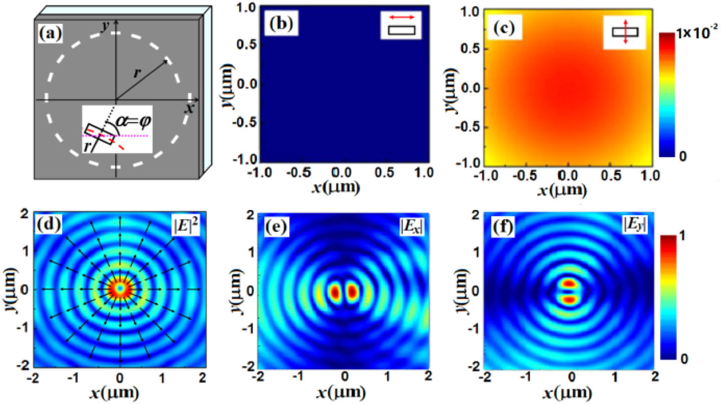
    Fig. 1. (a) Structure of the polarization converter consisting of rectangular holes equivalent to polarizers, and transmitted fields for (b), (c) a single rectangular hole and (d)–(f) this polarization converter.
    (a) Structure of the polarization converter based on rectangular holes equivalent to quarter-wave plates, and transmitted intensity distributions for (b), (c) a single rectangular hole and (d)–(f) the polarization converter. The inserted patterns in (b) and (c) are the phase distributions.
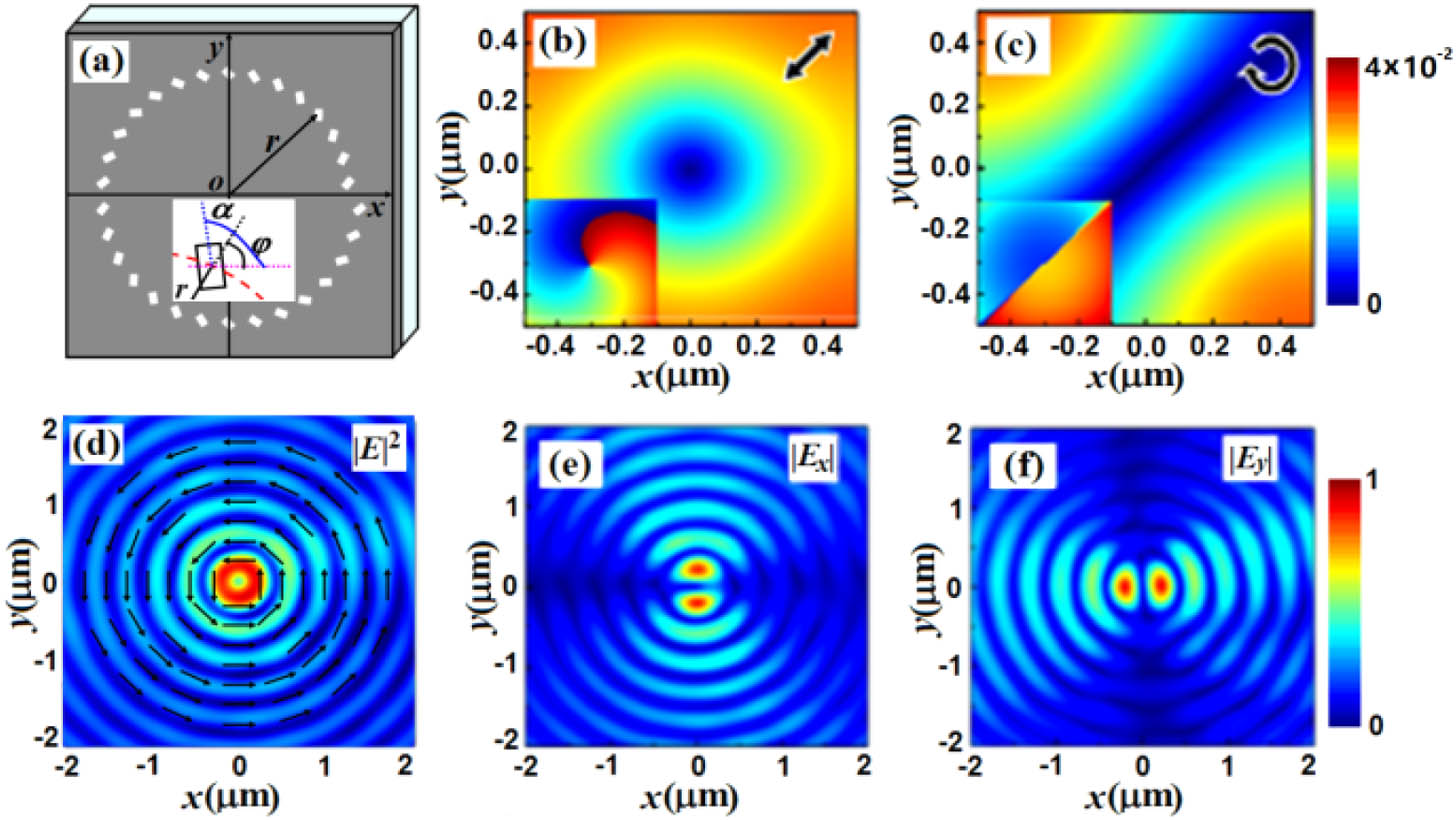
    Fig. 2. (a) Structure of the polarization converter based on rectangular holes equivalent to quarter-wave plates, and transmitted intensity distributions for (b), (c) a single rectangular hole and (d)–(f) the polarization converter. The inserted patterns in (b) and (c) are the phase distributions.
    (a) Structure of the third polarization converter based on the cross holes equivalent to half-wave plates, and (b), (c) transmitted phase distributions for a single cross hole and (d)–(f) the intensity distributions of the polarization converter.
    Fig. 3. (a) Structure of the third polarization converter based on the cross holes equivalent to half-wave plates, and (b), (c) transmitted phase distributions for a single cross hole and (d)–(f) the intensity distributions of the polarization converter.
    (a) Experiment setup, (b) SEM image of the polarization converter, and (c)–(h) its transmission fields, where QWP denotes the quarter-wave plate, P1 and P2 are polarizers, S represents the sample, and MO denotes the microscopy objective. The inserted red arrows in (c) and (f) denote the incident polarization direction, and the white ones in (d)–(h) denote the direction of polarizer P2.
    Fig. 4. (a) Experiment setup, (b) SEM image of the polarization converter, and (c)–(h) its transmission fields, where QWP denotes the quarter-wave plate, P1 and P2 are polarizers, S represents the sample, and MO denotes the microscopy objective. The inserted red arrows in (c) and (f) denote the incident polarization direction, and the white ones in (d)–(h) denote the direction of polarizer P2.
    Shuyun Teng, Qi Zhang, Han Wang, Lixia Liu, Haoran Lv. Conversion between polarization states based on a metasurface[J]. Photonics Research, 2019, 7(3): 246
    Download Citation