Abstract
Transmission of an anisotropic metasurface is analyzed in a polar base relying on the Jones calculus, and polarization conversion from the spatial uniform polarization to the spatial nonuniform polarization is explored. Simple and compact polarization converters based on rectangular holes or cross holes etched in silver film are designed, and polarization conversions from the linear and circular polarization to the radial and azimuthal polarization are realized. Numerical simulations of three designed polarization converters consisting of rectangular holes equivalent to polarizers and quarter- and half-wave plates, exhibit the perfect polarization conversion. The experiment results consistent with the simulations verify theoretic predictions. This study is helpful for designing metasurface polarization converters and expanding the application of a metasurface in polarization manipulations.1. INTRODUCTION
A metasurface consisting of subwavelength arrays makes surface-integrated photonics possible and provides an exciting platform for ultrathin optics or flat optics [1,2]. Because of the advantages of ultrathin thickness, low weight, ease-of-fabrication, and high efficiency, metasurfaces have gained wide attention, and different varieties of metasurfaces have applications in light manipulation, such as beam-steering devices [3], holography plates [4,5], ultrathin lenses [6,7], and invisibility cloaks [8], which are realized through controlling the amplitude, phase, and polarization of light.
Polarization is the nature of light. The generation of a polarization state and the conversion between different polarization states are usually realized by using a polarizer, a wave plate, and even an optical system. A well-designed optical metasurface can be used to change the polarization state. The metasurface structures used to convert the polarization states include high-contrast dielectric elliptical nanoposts [9], rectangular antenna arrays [10,11], V-shaped antennas [12], U-shaped aperture antennas [13], and orthogonal nanoslits or nanorods [14,15]. These studies realize the conversion between uniform polarization states based on the anisotropy of an optimized metastructure unit, and they provide experience for the detection of a polarization state and the conversion of different polarization states.
Although there is no one uniform theory for the design of a metasurface for polarization control, some studies relate to theoretical derivation in a Cartesian base and circular base [16–18]. Most importantly, there are few studies about the conversion of the spatial uniform polarization to spatial nonuniform polarization based on a simple metasurface [19–22]. In our former work [21,22], we designed polarization converters based on a field superposition and integration operation. The reverse process to ascertain the metastructure enhances the design difficulty and also makes the design mechanism of converters undetectable. In this paper, we aim to advance a general polarization conversion theory that can directly guide the design of a metasurface polarization converter for conversion of the spatial uniform polarization to spatial nonuniform polarization. Here, the mathematical expression of a transmission polarization state through the metasurface is given in the polar base using the Jones calculus, and the radial and azimuthal polarization is easily obtained based on the dependence relation of the transmission polarization state and the metastructure parameters and the illumination condition. Based on this theory, three metasurface polarization converters are proposed. The simulated results verify the theoretic prediction, and the practical experiment demonstrates the performance of metasurface polarization converters. The study of this paper provides the foundation for the design of metasurface polarization devices.
Sign up for Photonics Research TOC. Get the latest issue of Photonics Research delivered right to you!Sign up now
2. BASIC THEORY
The radial and azimuthal polarization states satisfy the orthogonal condition in the inner product space, like two orthogonal linear polarization states or the left- and right-handed circular polarization states. As we know, two orthogonal linear polarization states constitute the Cartesian base, and left- and right-handed circular polarization states form the circular base. Similarly, the radial and azimuthal polarization states make up the polar base. Assume that an optical metastructure is illuminated normally by a coherent plane wave, and the complex amplitudes of the incident and transmitted light can be described by the Jones calculus in the Cartesian base: where the amplitude components , , , and describe the incident and transmitted polarization states. They are connected through the transmission matrix , and they can be expressed as with the elements of the transmission matrix and denoting the transmission ratio of co-polarization states, and and representing the transmission ratio of cross-polarization states.
The incident and transmitted fields in the polar base can be written as and with being the change of basis matrix, and they satisfy Since the radial and azimuthal polarization states in the Cartesian base are denoted by and with being the angular position of the field, the change matrix and its reverse from the Cartesian base to the polar base can be expressed as For any incident polarization state in the polar base , the transmitted polarization state can be deduced by inserting Eq. (4) into Eq. (3). Naturally, the transmitted polarization state depends on the incident polarization state and the metasurface.
For the metasurface consisting of the anisotropic metastructure units with the period smaller than the wavelength, supposing and are the amplitudes of transmission electric fields along two major axes in the Cartesian base and is the phase delay of two electric fields along two major axes, its transmission matrix in the Cartesian base is with being the direction angle of the fast axis with respect to the axis. Thus, we can obtain the transmitted polarization state in the polar base with the incident field components and by where and .
Because the metastructure unit can be taken as a polarizer, , , and , then the transmitted polarization state in the polar base is written as When the transmission axis direction and the position angle of the metastructure unit are the same, namely, , this equation is the radial polarization state in the polar base. When the direction and position angles of the metastructure unit satisfy , this equation is just the azimuthal polarization state in the polar base. To ensure effective transmittance, the circular polarization light is usually chosen as the illumination light. Naturally, there is an additional spiral phase in the transmission for the incident circular polarization with and , and this spiral phase should be deleted to obtain the pure vector beam. If the linear polarization light is chosen as illumination light, the nonuniform intensity depending on the position of the unit should be considered and the relative complex structure is needed [22].
Because the metastructure unit can be taken as a quarter-wave plate, , , and the transmitted state in the polar base is simplified to When the incident light is the left-handed circularly polarized state with and , neglecting the constant term of , Eq. (8) is the radial polarization state of in the polar base with the fast axis direction and the position angle of the metastructure unit satisfying . When the incident light is the right-handed circularly polarized state with and , Eq. (8) is the azimuthal polarization state of in the polar base with the fast axis direction and the position angle of the metastructure unit also satisfying . Similarly, the additional spiral phase must be deleted to obtain the pure vector beam. This result is consistent with our former work [21], but the used analysis method is different, where the field superposition and the integration operation are used. Furthermore, as , the radial polarization state can also be obtained with the right-handed circularly polarized light illumination and the azimuthal polarization state is obtained with the left-handed circularly polarized light illumination.
If the metastructure unit is taken as a half-wave plate, , , and its transmission in the polar base is read as As the incident light takes the linear polarization light with the polarization angle and and , the transmitted state is the radial polarization (1, 0) with or the azimuthal polarization (0, 1) with . In fact, these two cases are equivalent to for and for . This indicates that for the same metastructure with , the transmitted state is azimuthal under the condition of and radial under the condition of . For circular polarization illumination, it is difficult to realize the conversion of the radial or azimuthal polarization with the simple metastructure.
This theoretical analysis in a polar base provides the direct relation of the transmission polarization with the incident polarization state and the metastructure unit, and it is the basis for the design of the metasurface polarization converters to convert the spatial uniform polarization to the spatial nonuniform polarization.
3. NUMERICAL SIMULATIONS
Nanometer rectangular holes have obvious anisotropy and, as examples, we design polarization converters based on rectangular holes equivalent to polarizers and quarter- and half-wave plates to convert the polarization state. The numerical simulations show that a rectangular hole with a larger length–width ratio like a long edge of 300 nm and a short edge of 100 nm can be taken as a polarizer, and a rectangular hole with a long edge of 310 nm and a short edge of 200 nm etched on silver with a thickness of 200 nm can be taken as a quarter-wave plate. The equivalent half-wave plate is a cross hole consisting of two orthogonal rectangular holes etched in silver film with a thickness of 220 nm, where one hole has a length of 600 nm and a width of 150 nm and the other has a length of 220 nm and a width of 180 nm.
On basis of the theoretic analysis in Section 2, we design first the polarization converter based on the rectangular holes equivalent to polarizers, and it can realize the conversion of circular polarization to radial polarization. To delete the spiral phase introduced by the circular polarization illumination, we arrange the rectangular holes along the Archimedes’ spiral satisfying , where is the initial radius and denotes the surface plasmon polariton wavelength. The short edge of the hole is toward the center of the polarization converter. Figure 1(a) gives the structure of this polarization converter, and the inserted magnified picture clearly shows the orientation of the hole, where the transmission axis is along the azimuthal angle. This structure is illuminated by the right-handed circularly polarized light with the wavelength of 0.633 μm. The polarization dependence for the transmission of a single rectangular hole is shown in Figs. 1(b) and 1(c), where the orthogonal linear polarization light illuminates. We can see that only the polarization light perpendicular to the long edge transmits as the polarizer acts. Figures 1(d)–1(f) show the transmitted intensity distribution and the and components through this polarization converter with . The arrows inserted in Fig. 1(d) denote the polarization direction of the field. These results indicate the transmission field is the radial polarization.
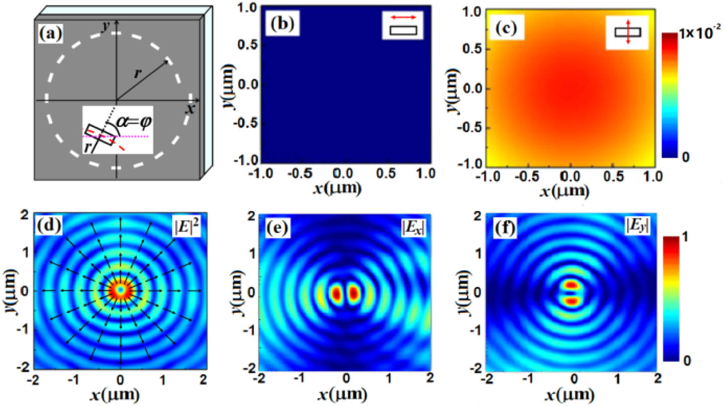
Figure 1.(a) Structure of the polarization converter consisting of rectangular holes equivalent to polarizers, and transmitted fields for (b), (c) a single rectangular hole and (d)–(f) this polarization converter.
Then, we design the polarization converter based on the rectangular holes equivalent to quarter-wave plates, and it converts circular polarization to azimuthal polarization. To delete the spiral phase introduced by the circular polarization illumination, we also arrange the rectangular holes along the Archimedes’ spiral. Figure 2(a) gives the structure of this polarization converter, where the starting radius of the Archimedes’ spiral takes 4 μm and the direction angle of the fast axis along the long edge of the rectangular hole and its position angle satisfy . The single rectangular hole can realize the conversion between the linear and circular polarization states, like the intensity distributions shown in Figs. 2(b) and 2(c), where the inserted patterns are the phase distributions and the inserted arrows denote the polarization direction of the incident light. Figures 2(d)–2(f) give the transmitted intensity and the and components through this polarization converter with the right-handed circularly polarized light illumination. Obviously, these results are also consistent with the characteristics of azimuthal polarization.

Figure 2.(a) Structure of the polarization converter based on rectangular holes equivalent to quarter-wave plates, and transmitted intensity distributions for (b), (c) a single rectangular hole and (d)–(f) the polarization converter. The inserted patterns in (b) and (c) are the phase distributions.
Figure 3 gives the polarization converter based on the cross holes, and it realizes the conversion of linear polarization to azimuthal polarization. Figure 3(a) shows the corresponding structure where the optimized cross hole is equivalent to a half-wave plate, and it can realize the conversion between the right-handed and left-handed circularly polarized light. The phase distributions of Figs. 3(b) and 3(c) verify this structure. The cross holes in Fig. 3(a) are arranged in one circle with a radius of 6 μm, and the fast axis along the long edge of the cross hole and its direction angle satisfy with . Figures 3(d)–3(f) give the transmission of this polarization converter with the incident linear polarization along the horizontal direction. The arrows inserted in Figs. 3(a)–3(c) denote the polarization direction of the incident light, and the arrows inserted in Fig. 3(d) denote the polarization direction of the field. The intensity distribution of Fig. 3(d) and the and components of Figs. 3(e) and 3(f) verify that the transmitted field is the azimuthal polarization.
Figure 3.(a) Structure of the third polarization converter based on the cross holes equivalent to half-wave plates, and (b), (c) transmitted phase distributions for a single cross hole and (d)–(f) the intensity distributions of the polarization converter.
It should be pointed out that the transmitted field distributions in Figs. 1–3 are simulated according to the finite difference time domain method [23], where the minimum spatial step is set at 2.5 nm and the perfect boundary condition is used. For the incident wavelength of 0.633 μm, the dielectric constant of silver takes the value given by Palik [24]. The observation planes for all the cases are set at 3 μm above the silver film.
4. EXPERIMENT MEASUREMENT
To test the polarization conversion theory and validate the performance of the designed polarization converters, we manufacture samples of metasurface polarization converters. Silver film with an ascertained thickness is first deposited on a glass substrate using the magnetron sputtering deposition method, and then the holes are etched in the silver film using the focused ion beam etching technique. One sample consists of 36 cross holes etched on the silver film with a thickness of 220 nm and arranged on the circle with , where one hole of the cross hole has a length of 600 nm and a width of 150 nm and the other hole has a length of 220 nm and a width of 180 nm. The arrangement of the cross holes is the same as the above theoretic description, and the device can realize the conversion of the linear polarization to the radial and azimuthal polarization. We then put this sample into the experimental setup of Fig. 4(a), and measure its transmission intensity distributions. The linear polarization beam from a He–Ne laser passes through the combination of a quarter-wave plate and polarizer P1 and changes the polarization direction. Then the beam illuminates the fabricated sample (S), and a microscopy objective (MO) is used to magnify and image the intensity distribution of the sample onto the received plane of a charge-coupled device (CCD) with No. DU-888U3. Polarizer P2 is used to analyze the polarization of the transmitted field.
Figure 4.(a) Experiment setup, (b) SEM image of the polarization converter, and (c)–(h) its transmission fields, where QWP denotes the quarter-wave plate, P1 and P2 are polarizers, S represents the sample, and MO denotes the microscopy objective. The inserted red arrows in (c) and (f) denote the incident polarization direction, and the white ones in (d)–(h) denote the direction of polarizer P2.
The SEM picture for the sample is given in Fig. 4(b). Figures 4(c)–4(e) show the transmitted intensity and its and components through the sample of Fig. 4(b) illuminated by the linearly polarized light with the polarization direction along the horizontal direction. We can see these results are the same as the ones in Figs. 3(d)–3(f), and this indicates that the azimuthally polarized light is really generated. Figures 4(f)–4(h) show that the incident polarization direction is along the vertical direction. We can see that these results are the same as the characteristics of the radially polarized light. In the practical measurement, the incident polarization direction must fit the orientation of the sample, so the accurate direction of polarizer P1 is needed to obtain the perfect experimental results. Any direction difference of the incident polarization as well as any fabrication defects in the holes may influence the symmetry of the fringes, as shown in Figs. 4(e) and 4(g). These results, however, are still good enough to demonstrate the theoretic prediction. Although only one polarization converter sample and its transmissions are exhibited here, the proposed theory is available for the design of other metasurface polarization converters. The experiment results in our former work in Ref. [21] give the verification.
5. CONCLUSIONS
In view of the potential applications of metasurfaces in integrated polarization devices, we advance a polarization conversion theory and design polarization converters based on a metasurface consisting of nanoholes. By analyzing the transmission of an anisotropic metasurface in a polar base relying on the Jones calculus, we deduce the general expression of the transmission polarization depending on the incident polarization and the metasurface. The theoretic analysis lays the foundation to design a metasurface polarization converter to convert a spatial uniform polarization to a spatial nonuniform polarization. Three examples of the polarization conversions verify the reliability of the theoretical analysis. Although some individual studies using different methods have the same results as our work, our proposed polarization conversion technique has widely instructive significance for designing metasurface polarized devices and our future work that will study achromatic polarization converters. We think this work is favorable for designing a functional polarization metasurface and expanding the application of metasurfaces in polarization manipulation.
References
[1] N. Yu, P. Genevet, M. A. Kats, F. Aieta, J. P. Tetienne, F. Capasso, Z. Gaburro. Light propagation with phase discontinuities: generalized laws of reflection and refraction. Science, 334, 333-337(2011).
[2] A. V. Kildishev, A. Boltasseva, V. M. Shalaev. Planar photonics with metasurfaces. Science, 339, 1232009(2013).
[3] L. Huang, X. Chen, H. Muhlenbernd, G. Li, B. Bai, Q. Tan, G. Jin, T. Zentgraf, S. Zhang. Dispersionless phase discontinuities for controlling light propagation. Nano Lett., 12, 5750-5755(2012).
[4] B. Walther, C. Helgert, C. Rockstuhl, F. Setzpfandt, F. Eilenberger, E. B. Kley, F. Lederer, A. Tunnermann, T. Pertsch. Spatial and spectral light shaping with metamaterials. Adv. Mater., 24, 6300-6304(2012).
[5] G. Zheng, H. Muhlenbernd, M. Kenney, G. Li, T. Zentgraf, S. Zhang. Metasurface holograms reaching 80% efficiency. Nat. Nanotechnol., 10, 308-312(2015).
[6] R. Z. Li, Z. Y. Guo, W. Wang, J. R. Zhang, K. Y. Zhou, J. L. Liu, S. L. Qu, S. T. Liu, J. Gao. Arbitrary focusing lens by holographic metasurface. Photon. Res., 3, 252-255(2015).
[7] M. Khorasaninejad, W. T. Chen, R. C. Devlin, J. Oh, A. Y. Zhu, F. Capasso. Metalenses at visible wavelengths: diffraction-limited focusing and subwavelength resolution imaging. Science, 352, 1190-1194(2016).
[8] X. Ni, Z. J. Wong, M. Mrejen, Y. Wang, X. Zhang. An ultrathin invisibility skin cloak for visible light. Science, 349, 1310-1314(2015).
[9] A. Arbabi, Y. Horie, M. Bagheri, A. Faraon. Dielectric metasurfaces for complete control of phase and polarization with subwavelength spatial resolution and high transmission. Nat. Nanotechnol., 10, 937-943(2015).
[10] F. Ding, Z. X. Wang, S. L. He, V. M. Shalaev, A. V. Kildishev. Broadband high-efficiency half-wave plate: a super-cell based plasmonic metasurface approach. ACS Nano, 9, 4111-4119(2015).
[11] Z. C. Liu, Z. C. Li, Z. Liu, H. Cheng, W. W. Liu, C. C. Tang, C. Z. Gu, J. J. Li, H. T. Chen, S. Q. Chen, J. G. Tian. Single-layer plasmonic metasurface half-wave plates with wavelength-independent polarization conversion angle. ACS Photon., 4, 2061-2069(2017).
[12] N. F. Yu, F. Aieta, P. Genevet, M. A. Kats, Z. Gaburro, F. Capasso, A. Broadband. A broadband, background-free quarter-wave plate based on plasmonic metasurfaces. Nano Lett., 12, 6328-6333(2012).
[13] M. Kang, T. H. Feng, H. T. Wang, J. Li. Wave front engineering from an array of thin aperture antennas. Opt. Express, 20, 15882-15890(2012).
[14] Y. Zhao, A. Alù. Manipulating light polarization with ultrathin plasmonic metasurfaces. Phys. Rev. B, 84, 205428(2011).
[15] Y. Zhao, A. Alù. Tailoring the dispersion of plasmonic nanorods to realize broadband optical meta-waveplates. Nano Lett., 13, 1086-1091(2013).
[16] E. Hasman, V. Kleiner, G. Biener, A. Niv. Polarization dependent focusing lens by use of quantized Pancharatnam–Berry phase diffractive optics. Appl. Phys. Lett., 82, 328-330(2003).
[17] C. Menzel, C. Rockstuhl, F. Lederer. An advanced Jones calculus for the classification of periodic metamaterials. Phys. Rev. A, 82, 053811(2010).
[18] F. Xiao, W. Shang, W. Zhu, L. Han, M. Premaratne, T. Mei, J. Zhao. Cylindrical vector beam-excited frequency-tunable second harmonic generation in a plasmonic octamer. Photon. Res., 6, 157-161(2018).
[19] P. Yu, S. Chen, J. Li, H. Cheng, Z. Li, W. Liu, B. Xie, Z. Liu, J. Tian. Generation of vector beams with arbitrary spatial variation of phase and linear polarization using plasmonic metasurfaces. Opt. Lett., 40, 3229-3232(2015).
[20] F. Yue, D. Wen, J. Xin, B. D. Gerardot, J. Li, X. Chen. Vector vortex beam generation with a single plasmonic metasurface. ACS Photon., 3, 1558-1563(2016).
[21] Q. Zhang, P. Y. Li, Y. Y. Li, H. Wang, L. X. Liu, Y. He, S. Y. Teng. Vector beam generation based on the nanometer-scale rectangular holes. Opt. Express, 25, 33480-33486(2017).
[22] Q. Zhang, H. Wang, L. X. Liu, S. Y. Teng. Generation of vector beams using spatial variation nanoslits with linearly polarized light illumination. Opt. Express, 26, 24145-24153(2018).
[23] A. Taflove, S. C. Hagness. Computational Electro Dynamics: The Finite-Difference Time-Domain Method(2000).
[24] E. D. Palik. Handbook of Optical Constants of Solids(1985).


