• Acta Optica Sinica
  • Vol. 37, Issue 12, 1213001 (2017)
Gongli Xiao1、2、*, Li Liu1, Hongyan Yang3, Xingguo Jiang1, Hongqing Wang1, Xiaogang Liu1, Haiou Li1, Fabi Zhang1, and Tao Fu1
Author Affiliations
  • 1 Guangxi Key Laboratory of Precision Navigation Technology and Application, Guilin University of Electronic Technology, Guilin, Guangxi 541004, China
  • 2 Guangxi Experiment Center of Information Science, Guilin, Guangxi 541004, China
  • 3 School of Computer Science and Information Security, Guilin University of Electronic Technology, Guilin, Guangxi 541004, China
  • show less
    DOI: 10.3788/AOS201737.1213001 Cite this Article Set citation alerts
    Gongli Xiao, Li Liu, Hongyan Yang, Xingguo Jiang, Hongqing Wang, Xiaogang Liu, Haiou Li, Fabi Zhang, Tao Fu. Light Transmission Characteristics of Metal Curved Waveguide Based on Microcavity Coupling Structures[J]. Acta Optica Sinica, 2017, 37(12): 1213001 Copy Citation Text show less
    Schematic diagram of the plasmonics bend waveguide filter based on microcavity coupling structure
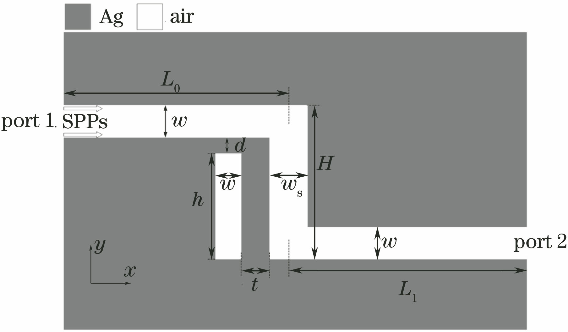
    Fig. 1. Schematic diagram of the plasmonics bend waveguide filter based on microcavity coupling structure
    (a) Transmission spectrogram of filters with (solid line) and without (dotted line) microcavity structures; electric field intensity distribution of the filter (b) without and (c) with resonant cavity
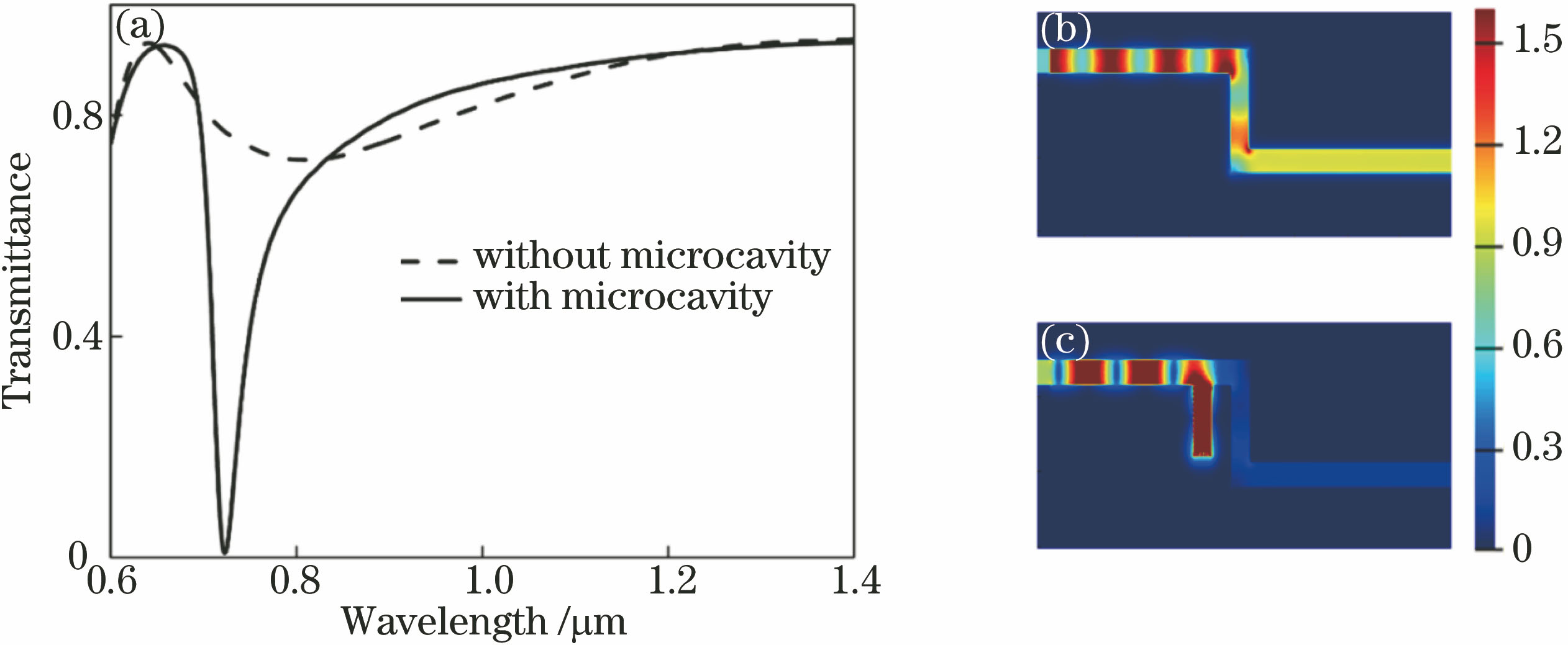
    Fig. 2. (a) Transmission spectrogram of filters with (solid line) and without (dotted line) microcavity structures; electric field intensity distribution of the filter (b) without and (c) with resonant cavity
    Transmission spectrogram of filter with different cavity lengths h under the conditions of d=12 nm, t=112 nm
    Fig. 3. Transmission spectrogram of filter with different cavity lengths h under the conditions of d=12 nm, t=112 nm
    (a) Transmission spectrogram and (b)~(e) electric field intensity distribution of the filters with different t under the conditions of d=12 nm, h=390 nm
    Fig. 4. (a) Transmission spectrogram and (b)~(e) electric field intensity distribution of the filters with different t under the conditions of d=12 nm, h=390 nm
    (a) Schematic diagram of the primary filter with the right cavity structure; (b) transmission spectra of the filter with different combinations of h and h0; transmission spectrogram of the MIM waveguide with (c) h=320 nm, h0=370 nm, (d) h=360 nm, h0=410 nm, (e) h=400 nm, h0=450 nm, (f) h=440 nm, h0=490 nm, (g) h=480 nm, h0=530 nm, (h) h=520 nm, h0=570 nm, (i) h=550 nm, h0=600 nm; (j) resonant wavelengths curve of peaks with the linear increase of resontor length in the plasma induced transparenc
    Fig. 5. (a) Schematic diagram of the primary filter with the right cavity structure; (b) transmission spectra of the filter with different combinations of h and h0; transmission spectrogram of the MIM waveguide with (c) h=320 nm, h0=370 nm, (d) h=360 nm, h0=410 nm, (e) h=400 nm, h0=450 nm, (f) h=440 nm, h0=490 nm, (g) h=480 nm, h0=530 nm, (h) h=520 nm, h0=570 nm, (i) h=550 nm, h0=600 nm; (j) resonant wavelengths curve of peaks with the linear increase of resontor length in the plasma induced transparenc
    Transmission spectrogram of the filter with different ▽h
    Fig. 6. Transmission spectrogram of the filter with different ▽h
    Gongli Xiao, Li Liu, Hongyan Yang, Xingguo Jiang, Hongqing Wang, Xiaogang Liu, Haiou Li, Fabi Zhang, Tao Fu. Light Transmission Characteristics of Metal Curved Waveguide Based on Microcavity Coupling Structures[J]. Acta Optica Sinica, 2017, 37(12): 1213001
    Download Citation