Abstract
Polarization aberration of hyper-numerical-aperture projection optics should be measured accurately in order to control it exactly and ensure favorable imaging performance. A hybrid calibration method combining the Fourier analysis method and the eigenvalue calibration method is proposed. A wide-view-angle Mueller polarimeter (WMP) is exemplified to demonstrate the capability of the proposed calibration method, which can calibrate the polarimeter and determine the error budget of polarizing elements in the polarimeter. In addition, an experimental setup and a WMP are developed in-house to implement the hybrid calibration method.The impact of polarization aberration on imaging performance is becoming more significant, especially in hyper-numerical-aperture (NA) systems[1–4]. Polarization aberration can be represented by the Jones pupil and the Mueller pupil[5], which can also be decomposed into diattenuation, retardance, and depolarization[6]. It is important to measure the polarization aberration accurately in order to control it reasonably and ensure good imaging performance[7,8]. However, the polarization aberration measurement with instrument calibration has not been mentioned.
Previous polarization aberration measurement methods based on scalar and vectorial aerial images can only extract the partial polarization aberration[9–11]. Recently, a full polarization aberration measurement method based on the aerial image has been published without taking the systemic measurement errors into account[12]. An in situ measurement method of polarization aberration was proposed by Furutono and Nomura, where the Mueller polarimeter was composed of a polarization mask as a polarization state generator (PSG) and a polarization monitor at the wafer side[13–15]. The monitor comprises collimating optics, a polarization state analyzer (PSA) composed of a rotating quarter-wave plate (QWP) and a fixed prism polarizer, as well as an image detector[15]. The pupils of collimating optics and projection optics are conjugated so that the variation of the light polarization state across the exit pupil of the projection optics, that is, polarization aberration, can be detected by the detector. However, the introduction of collimating optics leads to some measurement errors in the polarization aberration of the projection optics; hence, the polarization aberration of collimating optics should be calibrated. Many works have been done to calibrate high NA imaging systems[3,7]; these works need the normal or small angle incidence on the QWP. However, it is difficult to provide parallel light on the QWP under high NA measurement conditions, where the traditional calibration method is not applicable.
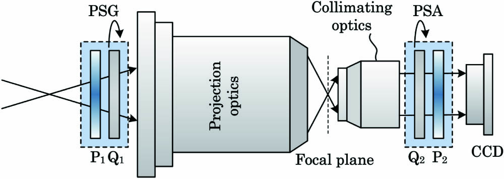
The schematic diagram of a wide-view-angle Mueller polarimeter (WMP) for measuring the Mueller pupil of projection optics is shown in Fig. 1. The WMP is mainly composed of a PSG, collimating optics, a PSA, and a charge-coupled device (CCD) camera[16]. The WMP is based on the dual-rotating-retarder polarimeter[16]. The PSG is composed of a fixed polarizer and a rotatable wide-view-angle QWP, . The PSA consists of a rotatable QWP, , and a linear polarizer, . Usually, the retardance of the wave plate depends on the incident angle; a large incident angle will cause large retardance. The traditional wave plate is only suitable for small incident angles. Therefore, it is necessary to use the wide-view-angle QWP, which is insensitive to the incidence angle. The wide-view-angle QWP consists of paired positive and negative birefringent plates to compensate the retardance variations. Since the WMP is based on the dual-rotating-retarder method, we need to rotate and four times, respectively, when measuring the Mueller matrix of the projection optics. In order to reduce the measurement error sensitivity, the rotation angles of the QWPs are optimized by minimizing the condition number of the instrument matrix[17]. The instrument errors of the WMP are mainly caused by PSG, PSA, and collimating optics, which should be calibrated before measuring the polarization aberration of projection optics.
Sign up for Chinese Optics Letters TOC. Get the latest issue of Chinese Optics Letters delivered right to you!Sign up now

Figure 1.Schematic diagram of a wide-view-angle Mueller polarimeter for measuring the Mueller pupil of projection optics.
In order to calibrate the WMP, especially for the collimating optics, a hybrid calibration method is proposed in this Letter. The calibration procedure includes two steps: the PSG and PSA are calibrated by the Fourier analysis method in the first step, while the collimating optics is calibrated by the eigenvalue calibration method (ECM) in the second step.
The Fourier analysis method is applied to calibrate five systematic errors in PSG and PSA with the absence of projection optics and collimating optics. The five systematic errors are the retardance errors and of and , the fast-axis azimuthal angle errors and of and , and the transmission axis azimuthal angle error of with respect to the transmission axis of . The QWPs should be rotated while calibrating these errors, where the rotation rates of and are 1:5, and the intensity can be given by[18]where is the rotation angle of . The Fourier coefficients and can be obtained from the measured intensities. According to the relationship with and , five systematic errors can be calculated[18]. Then, we could derive the calibrated Mueller matrices and of PSG and PSA, respectively.
After calibrating the PSG and PSA, the Mueller matrix , including the projection optics and collimating optics, can be acquired[17]: where is the measured intensity, and and are the Mueller matrices of projection optics and collimating optics, respectively.
The ECM is used to calibrate the collimating optics, which is based on the measurement of a set of reference samples with well-known Mueller matrices[19]. The reference samples should be placed between the projection optics and collimating optics. The common reference samples are air, a linear polarizer at 0° and 90°, and a QWP oriented at 30°[19,20]. In this step, a wide-view-angle QWP is used as the reference sample rather than a traditional QWP, which could satisfy the condition of ECM for obtaining the unique solution, as described in detail in Ref. [19].
In this step, the WMP can be divided into two groups in which the PSG is combined with projection optics as group 1 (called new PSG, with Mueller matrix ), and the collimating optics is combined with PSA as group 2 (called new PSA, with Mueller matrix ). The Mueller matrices and can be represented as
The Mueller matrices and can be calculated through ECM by solving equations of a couple of linear systems[19]. According to the derived and using the Fourier analysis method and Eqs. (3) and (4), and can be calculated as follows:
After performing the above steps, the collimating optics can be calibrated, and a high-accuracy measurement of projection optics can be achieved.
The proposed method is demonstrated by an experimental setup integrated with WMP, including collimating optics. The experimental setup for measuring the Mueller pupil of the projection optics is shown in Fig. 2. A He–Ne laser (632.8 nm) is used as the light source. The light beam is expanded by the beam expander and is then uniformly distributed using the uniformizer. A pinhole placed at the object plane produces the standard spherical wave. Then, the beam passes through the PSG, which is composed of a fixed polarizer (10LP-VIS-B polarizer, Newport) and a wide-view-angle QWP[21]. The retardance variation of the wide-view-angle QWP is maintained to within the angle of incidence. The beam with controlled polarization states illuminates the projection optics. Since the imaging beam emitted from the projection optics has a large NA, collimating optics matching the NA of projection optics is introduced to collimate the high-NA beam into a parallel beam. The parallel beam then passes through the PSA, which consists of a QWP (10RP04-24 waveplate, Newport) and a fixed polarizer (10LP-VIS-B polarizer, Newport). Finally, the modulated light is detected by a 14 bit CCD detector (Manta G-609 AVT). The projection optics is the Schwarzschild configuration, its NA is 0.5, and the reduction ratio is 40:1. The collimating optics is the catadioptric configuration. The transmission axes of the two polarizers are parallel, and the two QWPs of PSG and PSA are mounted on computer-controlled rotational stages (Newport URS100BCC and URS50BCC), respectively. In addition, the intensity measurements of CCD and the data process of calculating the Mueller pupils are automated using LabVIEW. The whole setup is installed on the anti-vibration table.
Figure 2.Experimental setup for measuring Mueller pupil of projection optics: 1, laser; 2, reflector; 3, beam expander; 4, uniformizer; 5, PSG; 6, projection optics; 7, focal plane; 8, collimating optics; 9, PSA; 10, CCD; 11, controller.
The proposed hybrid calibration method is used to calibrate the WMP. Firstly, the Fourier analysis method is performed without the projection optics and collimating optics. In this procedure, and rotate every 5° and 25°, simultaneously, and 36 intensity images are obtained. Then, we will derive the five errors, by which the calibrated PSG and PSA can be obtained. Table 1 shows the mean value corresponding to each error. It is noted that the calibrated results of PSG can be used in the following procedure because the retardance of the wide-view-angle QWP is insensitive to the incidence angle.
| Errors | Mean Value (°) |
|---|
| ε1 | 1.2034 |
| ε2 | 0.8425 |
| ε3 | −0.3839 |
| ε4 | −1.3407 |
| ε5 | −1.5470 |
Table 1. Parameter Errors of PSG and PSA
We use air as the sample to verify the calibrated PSG and PSA. In the measurement process of the air, 16 intensity images are measured while rotating the two QWPs. The rotation angles are and , which are optimized by minimizing the condition number[16]. The measured results of the air before and after calibration are shown in Fig. 3, and the mean values of each element are given in Eqs. (7) and (8). The root mean square (RMS) error of each matrix element is chosen to estimate the measurement errors of the Mueller matrix[22]. The measurement errors of air before and after calibration are 2.20% and 0.71%, respectively. After calibration, the measurement accuracy of air has been enhanced.
Figure 3.Mueller matrices over two-dimensional distribution of air (a) before calibration and (b) after calibration.
The QWP (Newport 10RP24-04) with its fast axis at 30° is also measured as a sample. Figure 4(a) gives the two-dimensional distribution of the Mueller matrix, which is consistent with the 30° QWP Mueller matrix form. In order to analyze the polarization properties of the QWP more intuitively, the matrix polar decomposition method[6] is applied to derive the individual properties, namely, diattenuation , total retardance , depolarization coefficient , linear retardance , fast-axis orientation , and circular retardance . The decomposition results are shown in Fig. 4(b). Meanwhile, we can also see from Fig. 4(b) that the QWP is a linear retarder, and the mean value of the linear retardance is 89.3069° (1.5587 rad), which is in agreement with its theoretical value of .
Figure 4.Mueller matrix over two-dimensional distribution of a QWP with its fast axis at 30° using the calibrated PSG and PSA. (a) The corresponding polarization parameters. (b) , diattenuation; , total retardance; , depolarization coefficient; , , linear retardance and fast-axis orientation; and , circular retardance.
The Mueller matrix , combining the projection optics and collimating optics, can also be measured by the same procedure as above. The ECM is employed to calibrate the collimating optics. The reference samples are placed between the projection optics and collimating optics in sequence, and 16 intensity images are obtained for each reference sample. The Mueller matrices and of new PSG and new PSA can be obtained by using the ECM. The Mueller matrices and of the collimating optics and projection optics can be calculated according to Eqs. (5) and (6). The calculated , , and are also shown in Fig. 5.
Figure 5.(a) Product of Mueller pupils of projection optics and collimating optics, ; (b) the Mueller pupil of collimating optics, ; (c) the Mueller pupil of projection optics, .
Through the proposed hybrid calibration method, the Mueller pupil of the projection optics can be measured accurately by eliminating the impact of the collimating optics. It can be seen from Fig. 5 that the polarization aberrations of the projection optics and collimating optics and are mainly represented by the retardance, which can be deduced from the sub-pupil in the lower right corner. However, the polarization aberration of the combination of the projection optics and collimating optics is relatively small. This is because the , , , and of the projection optics are similar to the collimating optics, but the signs are opposite.
The corresponding mean values, RMS, and peak-to-valley (PV) values of each sub-pupil of the Mueller pupil of projection optics are listed in Table 2. For comparison, the corresponding mean values, RMS, and PV values of each sub-pupil of are also shown in Table 2. Usually, the PV values could reveal the uniformity of the lens, and the larger the PV value, the more non-uniformity of the lens. It is noted that in Table 2, the element of has a larger PV value, which is mainly caused by the damage of the lens or the dust in the projection optics. The damaged point or the dust mainly introduces the depolarization of polarized light.
| Mp | M |
|---|
| Mean | [1.00000.01750.0010−0.00290.02350.9578−0.1266−0.00050.01280.10621.00770.0607−0.0040−0.0189−0.08050.9770] | [1.0000−0.01660.00200.0035−0.00520.9490−0.0066−0.0092−0.0003−0.00240.93790.00270.00210.0013−0.01240.9222] |
| RMS | [00.03000.02220.00780.03420.04640.13270.05150.04040.11050.05970.10980.01500.04700.11430.0373] | [00.02250.02160.01030.01370.05070.02550.00450.01250.01980.06160.04450.01060.03900.04810.0777] |
| PV | [00.69631.08620.18440.92581.93792.28260.42791.05842.43253.73501.31790.43040.51491.06902.7689] | [00.13330.20790.15300.13140.62150.21490.35780.14620.20950.64330.31390.14310.29850.31640.5632] |
Table 2. Corresponding Mean Values, RMS, and PV Values of Each Sub-Pupil of and in Fig. 5
The polar decomposition method is also applied to analyze the polarization aberration of the obtained , and , as shown in Fig. 6. It can be seen that the polarization properties of , , and are mainly represented by the total retardance . The diattenuation and depolarization coefficient are relatively small. mainly includes the linear retardance [Fig. 6(i)] and right circular retardance [Fig. 6(j)], and mainly consists of the linear retardance [Fig. 6(n)] and left circular retardance [Fig. 6(o)]. For , the primary retardance property is the linear retardance [Fig. 6(d)], because the circular retardance of projection optics [Fig. 6(j)] and collimating optics [Fig. 6(o)] have similar magnitudes but opposite orientation. The same trend can also be seen in the lower right sub-pupil in Fig. 5. It can be concluded that collimating optics has an effect on the measurement accuracy of projection optics. The proposed hybrid calibration method could calibrate the collimating optics and eliminate the influence of collimating optics.
Figure 6.Comparison of polarization parameters extracted from obtained , , and shown in Fig. 5.
In conclusion, we have proposed a hybrid calibration method for calibrating the WMP. The proposed method can calibrate the collimating optics as well as each polarizing element in the polarimeter. A WMP with collimating optics developed in-house is exemplified to demonstrate that the proposed method can provide a complete calibration and the polarization aberration measurement of the projection optics with high accuracy. This method can be extended to polarimetric measurements of other hyper-NA imaging systems, where the wide-view-angle QWPs need to be redesigned according to the wavelength and the NA.
References
[1] S. Mao, Y. Li, J. Jiang, S. Shen, K. Liu, M. Zheng. Chin. Opt. Lett., 16, 030801(2018).
[2] Y. Tu, X. Wang, S. Li, Y. Cao. Opt. Lett., 37, 2061(2012).
[3] P. R. T. Munro, P. Torok. Opt. Lett., 33, 2428(2008).
[4] H. He, Y. Ji, W. Shen. Chin. Opt. Lett., 10, S11102(2012).
[5] G. R. McIntyre, J. Kye, H. Levinson, A. R. Neureuther. J. Microlith. Microfab. Microsyst., 5, 3(2006).
[6] S. Y. Lu, R. A. Chipman. J. Opt. Soc. Am. A, 13, 1106(1996).
[7] C. Chen, X. Chen, H. Gu, H. Jiang, C. Zhang, S. Liu. Meas. Sci. Technol., 30, 025201(2019).
[8] J. Chen, L. Zhu, Z. Li. Chin. Opt. Lett., 16, 010501(2018).
[9] Y. Shiode, T. Ebiahara. Proc. SPIE, 6154, 615431(2006).
[10] L. Dong, Y. Li, X. Dai, H. Liu, K. Liu. Proc. SPIE, 9283, 928313(2014).
[11] Z. Xiang, Y. Li. Proc. SPIE, 10460, 104601W(2017).
[12] E. Li, Y. Li, N. Sheng, T. Li, Y. Sun, P. Wei. Opt. Express, 26, 32743(2018).
[13] H. Nomura, Y. Furutono. Proc. SPIE, 6924, 69241T(2008).
[14] H. Nomura. Thin Solid Films, 519, 2688(2011).
[15] H. Nomura, I. Higashikawa. Proc. SPIE, 7520, 752012(2009).
[16] L. Li, Y. Li, Q. Chi, K. Liu, X. Zhang, J. Li. Proc. SPIE, 9282, 928232(2014).
[17] M. H. Smith. Appl. Opt., 41, 2488(2002).
[18] D. H. Goldstein. Appl. Opt., 31, 6676(1992).
[19] E. Compain, S. Poirier, B. Drévillon. Appl. Opt., 38, 3490(1999).
[20] C. Macías-Romero, P. Torok. J. Europ. Opt. Soc. Rap. Public., 7, 12004(2012).
[21] J. Dong, Y. Li. J. Vac. Sci. Technol. B, 31, 011602(2013).
[22] K. Bhattacharyya, D. I. Serrano-García, Y. Otani. Opt. Commun., 392, 48(2017).