• Photonics Research
  • Vol. 5, Issue 6, 676 (2017)
Feng Wen1、2, Huapeng Ye2, Xun Zhang1, Wei Wang1, Shuoke Li1, Hongxing Wang1、*, Yanpeng Zhang1, and Cheng-wei Qiu2
Author Affiliations
  • 1Key Laboratory for Physical Electronics and Devices of the Ministry of Education & School of Science & Shaanxi Key Laboratory of Information Photonic Technique & Institute of Wide Bandgap Semiconductors, Xi’an Jiaotong University, Xi’an 710049, China
  • 2Department of Electrical and Computer Engineering, National University of Singapore, 4 Engineering Drive 3, Singapore 117583, Singapore
  • show less
    DOI: 10.1364/PRJ.5.000676 Cite this Article Set citation alerts
    Feng Wen, Huapeng Ye, Xun Zhang, Wei Wang, Shuoke Li, Hongxing Wang, Yanpeng Zhang, Cheng-wei Qiu. Optically induced atomic lattice with tunable near-field and far-field diffraction patterns[J]. Photonics Research, 2017, 5(6): 676 Copy Citation Text show less
    (a) Cascade-type three-level scheme with |a⟩[5S1/2(F=3)], |b⟩[5P3/2(F=3)], and |c⟩ (5D5/2) of Rb85 atoms [25], interacting with three laser beams: probe field EP and two lattice-forming fields E2(x) and E3(y). (b) The geometry of four laser beams applied upon a cold atoms ensemble along the z direction, and the corresponding near-field and far-field diffraction patterns of a probe field.
    Fig. 1. (a) Cascade-type three-level scheme with |a[5S1/2(F=3)], |b[5P3/2(F=3)], and |c (5D5/2) of Rb85 atoms [25], interacting with three laser beams: probe field EP and two lattice-forming fields E2(x) and E3(y). (b) The geometry of four laser beams applied upon a cold atoms ensemble along the z direction, and the corresponding near-field and far-field diffraction patterns of a probe field.
    (a) The periodical modulation of the lattice-forming laser due to the four-beam interference pattern with ΩC=8 MHz. The absorption spectrum and dispersion spectrum (b) at the nodes and (c) the antinodes of the lattice-forming laser.
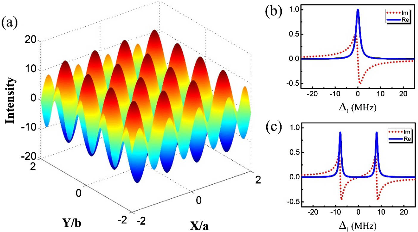
    Fig. 2. (a) The periodical modulation of the lattice-forming laser due to the four-beam interference pattern with ΩC=8  MHz. The absorption spectrum and dispersion spectrum (b) at the nodes and (c) the antinodes of the lattice-forming laser.
    Amplitude-type lattice, with settings ΩC=15 MHz, Δ1=0 MHz, and Δ2=0 MHz. (a) The amplitude and (b) the phase of the transmission function T(x,y) plotted over four space periods along x and y. (c) The corresponding normalized diffraction intensity I(θx,θy) as a function of sinθx and sinθy. (d) 2D transverse patterns corresponding to (c). Other parameters are γab=1 MHz, γac=0.1 MHz, a/λP=b/λP=4, L=10, and P=Q=1.
    Fig. 3. Amplitude-type lattice, with settings ΩC=15  MHz, Δ1=0  MHz, and Δ2=0  MHz. (a) The amplitude and (b) the phase of the transmission function T(x,y) plotted over four space periods along x and y. (c) The corresponding normalized diffraction intensity I(θx,θy) as a function of sinθx and sinθy. (d) 2D transverse patterns corresponding to (c). Other parameters are γab=1  MHz, γac=0.1  MHz, a/λP=b/λP=4, L=10, and P=Q=1.
    Phase-type lattice, with settings ΩC=15 MHz, Δ1=10 MHz, and Δ2=0 MHz. (a) The amplitude and (b) the phase of the transmission function T(x,y) plotted over four space periods along x and y. (c) The corresponding normalized diffraction intensity I(θx,θy) as a function of sin θx and sin θy. (d) 2D transverse patterns corresponding to (c). (e) The amplitude (solid curve) and the phase (dashed curve) of the transmission function T(x,y) as a function of x within a single space period. Other parameters are γab=1 MHz, γac=0.2 MHz, a/λP=b/λP=4, L=10, and P=Q=1.
    Fig. 4. Phase-type lattice, with settings ΩC=15  MHz, Δ1=10  MHz, and Δ2=0  MHz. (a) The amplitude and (b) the phase of the transmission function T(x,y) plotted over four space periods along x and y. (c) The corresponding normalized diffraction intensity I(θx,θy) as a function of sinθx and sinθy. (d) 2D transverse patterns corresponding to (c). (e) The amplitude (solid curve) and the phase (dashed curve) of the transmission function T(x,y) as a function of x within a single space period. Other parameters are γab=1  MHz, γac=0.2  MHz, a/λP=b/λP=4, L=10, and P=Q=1.
    Normalized diffraction intensity IP(θx0,θy0) (solid line), IP(θx1,θy0) (dashed line), and IP(θx1,θy1) (dashed–dotted line) as a function of ΩC with (a) amplitude lattice with Δ1=0 MHz, and Δ2=0 MHz and (b) phase-type lattice Δ1=10 MHz, and Δ2=0 MHz. Other parameters are γab=1 MHz, γac=0.2 MHz, a/λP=b/λP=4, L=10, and P=Q=1.
    Fig. 5. Normalized diffraction intensity IP(θx0,θy0) (solid line), IP(θx1,θy0) (dashed line), and IP(θx1,θy1) (dashed–dotted line) as a function of ΩC with (a) amplitude lattice with Δ1=0  MHz, and Δ2=0  MHz and (b) phase-type lattice Δ1=10  MHz, and Δ2=0  MHz. Other parameters are γab=1  MHz, γac=0.2  MHz, a/λP=b/λP=4, L=10, and P=Q=1.
    Near-field diffraction pattern in the case of (a) amplitude-type lattice and (b) phase-type lattice, and (a1)–(a4), (b1)–(b4) Talbot imaging at Z=0, zT/2, 2zT/3, and zT, respectively.
    Fig. 6. Near-field diffraction pattern in the case of (a) amplitude-type lattice and (b) phase-type lattice, and (a1)–(a4), (b1)–(b4) Talbot imaging at Z=0, zT/2, 2zT/3, and zT, respectively.
    Feng Wen, Huapeng Ye, Xun Zhang, Wei Wang, Shuoke Li, Hongxing Wang, Yanpeng Zhang, Cheng-wei Qiu. Optically induced atomic lattice with tunable near-field and far-field diffraction patterns[J]. Photonics Research, 2017, 5(6): 676
    Download Citation