
Changmin Ahn, Yongjin Na, Minji Hyun, Jinho Bae, Jungwon Kim, "Synchronization of an optical frequency comb and a microwave oscillator with 53 zs/Hz1/2 resolution and 10-20-level stability," Photonics Res. 10, 365 (2022)
- Photonics Research
- Vol. 10, Issue 2, 365 (2022)
Abstract
1. INTRODUCTION
An optical frequency comb, which consists of evenly spaced frequency components in the optical domain, connects the optical and microwave frequencies in a coherent way [1,2]. This unique property has facilitated its utilization to various microwave photonic applications. Precise and stable synchronization between an optical frequency comb (in forms of femtosecond mode-locked lasers or microresonator-based Kerr combs) and a microwave source is important for various fields. It is highly desirable for coherent microwave networks over kilometer (km) distances for very-long-baseline interferometers (VLBIs) [3,4], high-performance optoelectronic phase-locked loops (PLLs) for telecommunications [5], and as a direct link between microwave clocks and optical frequency combs [6]. In particular, it plays a critical role for ultrafast science facilities, such as X-ray free-electron lasers (XFELs) [7,8] and ultrafast electron diffraction (UED) sources [9,10], where precise and stable synchronization between multiple femtosecond mode-locked lasers and microwave-driven cavities and photoguns is required.
Traditionally, the timing error between an optical frequency comb and a microwave source was measured using a microwave mixer after extracting a microwave from the optical pulse train with a high-bandwidth photodetector and a bandpass filter [11–15]. While this method has been widely used, it has limited timing resolution and stability because of the saturation and amplitude-to-phase conversion of photodiodes and the limited phase discrimination resolution of microwave mixers. As an alternative, timing detection in the optical domain using electro-optic sampling with an interferometer has been studied for precise timing discrimination and optical-microwave synchronization [16–22]. There are two optical-microwave timing detection concepts: direct conversion of the timing error into intensity imbalance [16–18,22] and synchronous detection using half of the repetition rate as the modulation signal [19–21]. The former method, which is also collectively called as the electro-optic sampling-based timing detection (EOS-TD) method, has demonstrated subfemtosecond optical-microwave timing synchronization performance [17,22] and high amplitude-to-phase suppression ratio [23] by introducing balanced detection. This approach has been actively used for a variety of applications such as low-noise microwave generation [24,25], long-distance timing transfer [26,27], comb stabilization [6,28], time-of-flight sensing [29], laser-microwave synchronization for UED [30], and fiber link stabilization for FELs [31]. Despite its excellent performance, there was more than 10 dB difference in synchronization performance between the expected shot-noise-limited noise floor and the measured residual noise floor, indicating that there is still potential for improvement.
In this paper, we demonstrate a shot-noise-limited synchronization performance of the EOS-TD method, which resulted in a single-sideband (SSB) residual phase noise floor of
Sign up for Photonics Research TOC. Get the latest issue of Photonics Research delivered right to you!Sign up now
2. ELECTRO-OPTIC SAMPLING-BASED TIMING DETECTORS
In this section, we will briefly overview the schematic and operation principles of the EOS-TDs. In essence, the EOS-TD converts the timing error between zero-crossings of the microwave signal and ultrashort optical pulses (
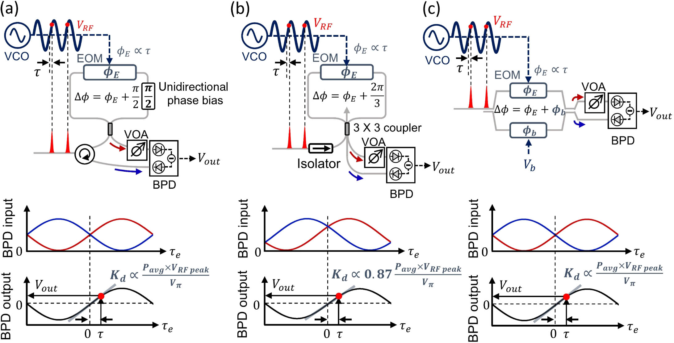
Figure 1.Schematic of EOS-TDs. (a) Sagnac-loop-based EOS-TD with unidirectional phase bias, (b)
The same EOS-TD principle can be implemented with different configurations. For example, a
3. EXPERIMENT METHODS
Figure 2 shows an overall setup of the EOS-TD-based timing synchronization experiment. A 250 MHz mode-locked erbium-doped fiber laser oscillator (FC1500-250-ULN, MenloSystems GmbH) was used for the optical pulse source. The optical signal goes through dispersion compensating fibers (DCFs), which adjust the pulse duration incident at the EOM below 1 ps for accurate electro-optic sampling. We multiplied the pulse repetition rate using a multistage (
![]()
Figure 2.Experimental setup schematic of the optical–microwave timing synchronization. DCF, dispersion compensating fiber; MZI, Mach–Zehnder interferometer; LF, loop filter; MDL, manual delay line; BPD, balanced photodetector; PD, photodetector; EDFA, erbium-doped fiber amplifier; RIN, relative intensity noise; LD, laser diode; VCO, voltage-controlled oscillator; BPF, bandpass filter; EOM, electro-optic phase modulator; RF amp, RF amplifier.
For constructing the synchronization PLL, the output voltage of the in-loop EOS-TD is fed to a loop filter (LB-1005, Newfocus), which is a PI controller. The controller output is applied to an 8 GHz VCO (HMC-C200, Hittite), which is used as a slave microwave oscillator. Here, the VCO frequency should be matched to the multiples of pulse repetition rate (
The residual phase noise of the synchronization PLL was evaluated by the out-of-loop EOS-TD. The voltage noise power spectra were measured by a fast Fourier transform (FFT) spectrum analyzer (SR760, Stanford Research Systems) and an RF spectrum analyzer (E4440A, Keysight) for the offset frequency range of 1 Hz–100 kHz and 100 kHz–10 MHz, respectively, and converted to the equivalent timing and phase noise power spectral densities (PSDs). The measurement was performed at the zero-crossing of the out-of-loop EOS-TD output by controlling the relative optical path difference with a manual delay line (MDL in Fig. 2) to maximize the detection sensitivity and suppress the impact of intensity noise.
4. MEASUREMENT RESULTS
A. Effect of Bandpass Filtering of the Microwave Signal
In this work, we first checked the effect of RF bandpass filtering. Ideally, the microwave oscillator should generate a single-tone microwave (8 GHz in this work); however, as shown in Fig. 3(a), harmonic modes of 8 GHz, such as 16 GHz and 24 GHz, are also generated due to the nonlinearity of the oscillator. As the RF spectrum of the frequency comb contains the harmonics of its repetition rate, harmonic modes of the microwave oscillator (
![]()
Figure 3.(a) RF spectrum of the 8 GHz VCO output without (black) and with RF bandpass filtering (red). (b) SSB residual phase noise at 8 GHz carrier [curve (i), curve (iii)] without and [curve (ii), curve (iv)] with the RF bandpass filter when repetition rate is 250 MHz and 2 GHz, respectively. Here, the dashed line is the shot limit of the in-loop EOS-TD.
We compared the phase noise with and without the RF-BPF for both 250 MHz and 2 GHz pulse repetition-rate cases [Fig. 3(b)]. When the repetition rate is 250 MHz, the phase noise PSDs at 100 kHz offset frequency without [curve (i)] and with [curve (ii)] RF-BPF were measured to be
B. Optical Pulse Repetition-Rate Dependence
The repetition-rate dependence of the EOS-TD is also studied. For this, we conducted the same experiment with different repetition rates of 250 MHz, 500 MHz, 1 GHz, and 2 GHz by changing the number of MZI pulse interleaving stages in Fig. 2. For each case, the pulse duration at the EOS-TD input is adjusted to be
Figure 4(a) shows the measured detection sensitivity (
![]()
Figure 4.(a) Change of detection sensitivity for different pulse repetition rates. (b) SSB phase noise floor at 8 GHz carrier [curve (i)] without MZI, [curve (ii)] with 1-stage, [curve (iii)] 2-stage, and [curve (iv)] 3-stage MZI, respectively.
Figure 4(b) shows the measured SSB phase noise floors for different repetition-rate conditions, where curves (i), (ii), (iii), and (iv) correspond to the residual phase noise floor with pulse repetition rate of 250 MHz, 500 MHz, 1 GHz, and 2 GHz, respectively. The residual phase noise at 100 kHz offset frequency decreases from
Figure 5 shows the measured SSB residual phase noise and integrated rms timing jitter of the EOS-TD-based timing synchronization when both the RF-BPF and three-stage MZI are employed. Curves (i) and (ii) show the free-running VCO phase noise and the residual phase noise for comb-microwave synchronization, respectively. The residual phase noise at 8 GHz carrier reaches
![]()
Figure 5.SSB phase noise at 8 GHz carrier and integrated timing jitter with the experimental setup of Fig.
C. Impact of the Lead Compensator
As mentioned in the previous section, the high resonance peak caused by the control loop makes large integrated timing jitter for a higher integration frequency range. Therefore, we designed an additional lead compensator to increase the phase margin at a few megahertz (MHz), which leads to a lower resonance peak. The lead compensator was designed using passive components, including a resistor and a capacitor, and placed before the loop filter. For the experiment, the RF-BPF and three-stage MZI were used.
The measurement results are shown in Fig. 6. Curves (i) and (ii) indicate the SSB residual phase noise with and without the lead compensator, respectively. For comparison, the phase noise of the free-running VCO is also shown [curve (iii)]. As there is no change in the in-loop measurement noise floor, two data have the same phase noise of
![]()
Figure 6.SSB residual phase noise at 8 GHz carrier and integrated timing jitter. Curve (i), curve (ii) indicate the residual phase noise with and without the lead compensator, respectively. The phase noise of the VCO is also shown [curve (iii)]. Integrated timing jitters of curves (i), (ii) correspond to blue and red curves, respectively.
D. Long-Term Stability Evalution
The long-term stability of the EOS-TD-based optical-microwave timing synchronization system was evaluated (Fig. 7). Note that this experiment was conducted with the RF BPF and the three-stage MZI. The relative timing error was acquired by monitoring the out-of-loop EOS-TD output using a data acquisition board with 100 Hz sampling rate. Note that we placed the experimental setup (except the comb source) inside a polycarbonate shielding box to isolate the external effects such as temperature change and air fluctuations. For the long-term measurement, we turned on the entire setup and waited for
![]()
Figure 7.Long-term stability evaluation results. (a) Relative timing error measured for 12 h, (b) residual phase noise and integrated jitter down to 1 mHz offset frequency, and (c) fractional frequency instability (overlapping Allan deviation).
We first used the same test condition as that for obtaining the short-term measurement results (Figs. 3–6). As can be seen in Fig. 7(c), there is an instability bump around 0.2–20 s averaging time (the “with EDFA” case). Note that similar bump in this time scale was also observed and reported by other previous research, and it was attributed to technical noise induced by feedback control [33,34]. In this work, we carefully examined the possible causes of the frequency instability bump in our synchronization system and found that gain condition of the EDFA pump’s thermoelectric cooler (TEC) control was the primary cause. Thus, we also evaluated the long-term synchronization performances without the EDFA. Comparisons of the timing drift over 12 h, the equivalent phase noise PSD down to 1 mHz offset frequency, and the frequency instability over 10,000 s averaging time are shown in Figs. 7(a), 7(b), and 7(c), respectively.
First, as shown in Fig. 7(a), removing the EDFA greatly reduces the thickness of the timing drift data, owing to significantly reduced noise in the 0.2–20 s time scale. The integrated rms timing drift over 12 h is 319 as (without EDFA) and 330 as (with EDFA). The temperature of the EOS-TD was also monitored and maintained within 0.06–0.2 K over 12 h. As the measured timing drift shows a certain degree of correlation with the temperature (with
Figure 7(b) shows the residual phase noise and integrated jitter extended down to 1 mHz offset frequency. When the EDFA is used, a bump in phase noise in the 2 mHz–1 Hz range is clearly visible, which corresponds to the thick timing drift data [in Fig. 7(a)] and bump in frequency instability [in Fig. 7(c)]. By removing the EDFA, the bump in the 2 mHz–1 Hz frequency range is removed, and the phase noise follows a slope of
In Fig. 7(c), the relative timing error was also converted into fractional frequency instability in terms of overlapping Allan deviation. Fractional frequency instability reached
5. CONCLUSION
In summary, we have demonstrated the shot-noise-limited performance of the EOS-TD-based synchronization between an optical frequency comb and a microwave oscillator, which enabled unprecedented residual phase noise floor of
References
[1] T. Udem, R. Holzwarth, T. W. Hänsch. Optical frequency metrology. Nature, 416, 233-237(2002).
[2] A. D. Ludlow, M. M. Boyd, J. Ye, E. Peik, P. O. Schmidt. Optical atomic clocks. Rev. Mod. Phys., 87, 637-701(2015).
[3] C. Clivati, R. Aiello, G. Bianco. Common-clock very long baseline interferometry using a coherent optical fiber link. Optica, 7, 1031-1037(2020).
[4] C. Clivati, R. Ambrosini, T. Artz, A. Bertarini, C. Bortolotti, M. Frittelli, F. Levi, A. Mura, G. Maccaferri, M. Nanni, M. Negusini, F. Perini, M. Roma, M. Stagni, M. Zucco, D. Calonico. A VLBI experiment using a remote atomic clock via a coherent fibre link. Sci. Rep., 7, 40992(2017).
[5] J. C. Scheytt, D. Wrana, M. Bahmanian, I. Kallfass. Ultra-low phase noise frequency synthesis for THz communications using optoelectronic PLLs. 3rd International Workshop on Mobile Terahertz Systems (IWMTS), 1-4(2020).
[6] S. Zhang, J. Wu, J. Leng, S. Lai, J. Zhao. Highly precise stabilization of intracavity prism-based Er:fiber frequency comb using optical-microwave phase detector. Opt. Lett., 39, 6454-6457(2014).
[7] P. Emma, R. Akre, J. Arthur, R. Bionta. First lasing and operation of an ångstrom-wavelength free-electron laser. Nat. Photonics, 4, 641-647(2010).
[8] S. Schulz, I. Grguraš, C. Behrens, H. Bromberger, J. T. Costello, M. K. Czwalinna, M. Felber, M. C. Hoffmann, M. Ilchen, H. Y. Liu, T. Mazza, M. Meyer, S. Pfeiffer, P. Predki, S. Schefer, C. Schmidt, U. Wegner, H. Schlarb, A. L. Cavalieri. Femtosecond all-optical synchronization of an X-ray free-electron laser. Nat. Commun., 6, 5938(2015).
[9] J. Shin, H. Kim, S. Park, H. Bark, K. Oang, K. Jang, K. Lee, F. Rotermund, Y. Jeong, J. Kim. Sub-10-fs timing for ultrafast electron diffraction with THz-driven streak camera. Laser Photon. Rev., 15, 2000326(2021).
[10] S. P. Weathersby, G. Brown, M. Centurion, T. F. Chase, R. Coffee, J. Corbett, J. P. Eichner, J. C. Frisch, A. R. Fry, M. Gühr, N. Hartmann, C. Hast, R. Hettel, R. K. Jobe, E. N. Jongewaard, J. R. Lewandowski, R. K. Li, A. M. Lindenberg, I. Makasyuk, J. E. May, D. McCormick, M. N. Nguyen, A. H. Reid, X. Shen, K. Sokolowski-Tinten, T. Vecchione, S. L. Vetter, J. Wu, J. Yang, H. A. Dürr, X. J. Wang. Mega-electron-volt ultrafast electron diffraction at SLAC National Accelerator Laboratory. Rev. Sci. Instrum., 86, 073702(2015).
[11] R. P. Scott, C. Langrock, B. H. Kolner. High-dynamic-range laser amplitude and phase noise measurement techniques. IEEE J. Sel. Top. Quantum Electron., 7, 641-655(2001).
[12] F. Kiewiet, A. Kemper, O. Luiten, G. Brussaard, M. J. van der wiel. Femtosecond synchronization of a 3 GHz RF oscillator to a mode-locked Ti:sapphire laser. Nucl. Instrum. Methods Phys. Res. Sect. A, 484, 619-624(2002).
[13] Q. Du, Y. Du, L. Yan, W. Huang, J. Li, C. Tang. Precise control and measurement of Laser-RF synchronization for Thomson-scattering X-ray source. Nucl. Instrum. Methods Phys. Res. Sect. A, 637, S137-S140(2011).
[14] K. Gumerlock, J. Frisch, B. Hill, J. May, D. Nelson, S. Smith. A low-cost, high-reliability femtosecond laser timing system for LCLS. 36th International Free Electron Laser Conference (FEL), 917-921(2014).
[15] M. Titberidze, M. Felber, T. Lamb, R. Loch, C. Sydlo, H. Schlarb. Fs level laser-to-RF synchronization at REGAE. J. Phys. Conf. Ser., 874, 012085(2017).
[16] J. Kim, M. H. Perrott, F. X. Kaertner. Femtosecond synchronization of RF-signals with optical pulse trains. Opt. Lett., 79, 768-770(2004).
[17] K. Jung, J. Kim. Subfemtosecond synchronization of microwave oscillators with mode-locked Er-fiber lasers. Opt. Lett., 37, 2958-2960(2012).
[18] M. Endo, T. D. Shoji, T. R. Schibli. High-sensitivity optical to microwave comparison with dual-output Mach-Zehnder modulators. Sci. Rep., 8, 4388(2018).
[19] M. Y. Peng, A. Kalaydzhyan, F. X. Kärtner. Balanced optical-microwave phase detector for sub-femtosecond optical-RF synchronization. Opt. Express, 22, 21702-21711(2014).
[20] M. Xin, K. Şafak, M. Y. Peng, A. Kalaydzhyan, W. T. Wang, O. D. Mücke, F. X. Kärtner. Attosecond precision multi-kilometer laser-microwave network. Light Sci. Appl., 6, e16187(2017).
[21] A. Nejadmalayeri, F. Kärtner. Mach-Zehnder based balanced optical microwave phase detector. Conference on Lasers and Electro-Optics, CTu2A.1(2012).
[22] C.-G. Jeon, Y. Na, B.-W. Lee, J. Kim. Simple-structured, subfemtosecond- resolution optical-microwave phase detector. Opt. Lett., 43, 3997-4000(2018).
[23] M. Lessing, H. S. Margolis, C. T. A. Brown, P. Gill, G. Marra. Suppression of amplitude-to-phase noise conversion in balanced optical-microwave phase detectors. Opt. Express, 21, 27057-27062(2013).
[24] D. Hou, X. P. Xie, Y. L. Zhang, J. T. Wu, Z. Y. Chen, J. Y. Zhao. Highly stable wideband microwave extraction by synchronizing widely tunable optoelectronic oscillator with optical frequency comb. Sci. Rep., 3, 3509(2013).
[25] M. Bahmanian, J. C. Scheytt. A 2–20-GHz ultralow phase noise signal source using a microwave oscillator locked to a mode-locked laser. IEEE Trans. Microw. Theory Tech., 69, 1635-1645(2021).
[26] X. Chen, J. Zhang, J. Lu, X. Lu, X. Tian, B. Liu, H. Wu, T. Tang, K. Shi, Z. Zhang. Feed-forward digital phase compensation for long-distance precise frequency dissemination via fiber network. Opt. Lett., 40, 371-374(2015).
[27] X. Chen, J. Lu, Y. Cui, J. Zhang, X. Lu, X. Tian, C. Ci, B. Liu, H. Wu, T. Tang, K. Shi, Z. Zhang. Simultaneously precise frequency transfer and time synchronization using feed-forward compensation technique via 120 km fiber link. Sci. Rep., 5, 18343(2015).
[28] B. Ning, S. Zhang, D. Hou, J. Wu, Z. Li, J. Zhao. High-precision distribution of highly stable optical pulse trains with 8.8×10⁻¹⁹ instability. Sci. Rep., 4, 5109(2014).
[29] Y. Na, C. G. Jeon, C. Ahn, M. Hyun, D. Kwon, J. Shin, J. Kim. Ultrafast, sub-nanometre-precision and multifunctional time-of-flight detection. Nat. Photonics, 14, 355-360(2020).
[30] H. Yang, B. Han, J. Shin, D. Hou, H. Chung, I. Baek, Y. Jeong, J. Kim. 10-fs-level synchronization of photocathode laser with RF-oscillator for ultrafast electron and X-ray sources. Sci. Rep., 7, 39966(2017).
[31] K. Jung, J. Lim, J. Shin, H. Yang, L. Chen, F. X. Kaertner, H. Kang, C. Min, J. Kim. Remote laser-microwave synchronization over kilometer-scale fiber link with few-femtosecond drift. J. Lightwave Technol., 32, 3742-3748(2014).
[32] A. Haboucha, W. Zhang, T. Li, M. Lours, A. N. Luiten, Y. Le Coq, G. Santarelli. Optical-fiber pulse rate multiplier for ultralow phase-noise signal generation. Opt. Lett., 36, 3654-3656(2011).
[33] J. Millo, R. Boudot, M. Lours, P. Y. Bourgeois, A. N. Luiten, Y. Le Coq, Y. Kersale, G. Santarelli. Ultra-low noise microwave extraction from fiber-based optical frequency comb. Opt. Lett., 34, 3707-3709(2009).
[34] N. Hinkley, J. A. Sherman, N. B. Phillips, M. Schioppo, N. D. Lemke, K. Beloy, M. Pizzocaro, C. W. Oates, A. D. Ludlow. An atomic clock with 10−18 instability. Science, 341, 1215-1218(2013).
[35] T. Nakamura, J. Davila-Rodriguez, H. Leopardi, J. A. Sherman, T. M. Fortier, X. Xie, J. C. Campbell, W. F. McGrew, X. Zhang, Y. S. Hassan, D. Nicolodi, K. Beloy, A. D. Ludlow, S. A. Diddams, F. Quinlan. Coherent optical clock down-conversion for microwave frequencies with 10−18 instability. Science, 368, 889-892(2020).


Set citation alerts for the article
Please enter your email address

© Copyright 2018-2021 | Chinese Laser Press. All Rights Reserved 沪ICP备15018463号-20