
Biao Chen, Xiahui Zeng, Xiyao Chen, Yuanyuan Lin, Yishen Qiu, Hui Li. Tunable dual-band infrared polarization filter based on a metal-dielectric-metal compound rectangular strip array[J]. Chinese Optics Letters, 2015, 13(3): 031301
- Chinese Optics Letters
- Vol. 13, Issue 3, 031301 (2015)
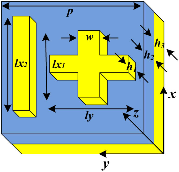
Fig. 1. Schematic of the polarization filter cell structure. Top layer is a metal compound in rectangular strips. Thickness and the width of the three rectangular strips is h 1 = 20 nm w = 100 nm MgF 2 MgF 2 h 2 = 50 nm h 3 = 180 nm x y p = 600 nm
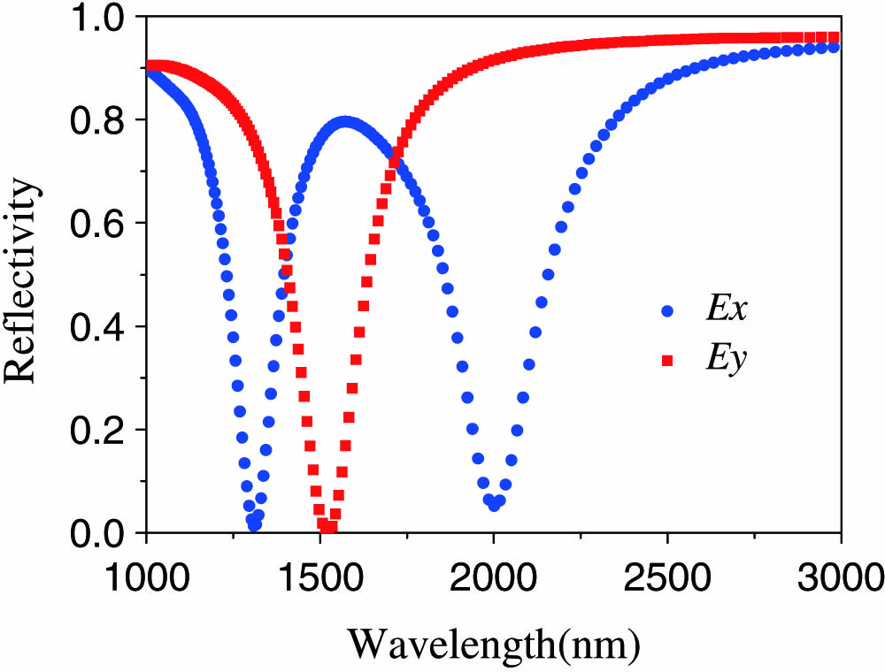
Fig. 2. Simulated reflection spectra of the filter with l x 1 = 300 nm l x 2 = 450 nm l y = 350 nm E x E y
Fig. 3. Distributions of the electric field E z E x E y
Fig. 4. Simulated reflection spectra of the filter structure as a function of the length; (a) l x 1 Δ l x 1 = 20 nm l x 2 l x 2 Δ l x 2 = 20 nm l x 1 E x
Fig. 5. Simulated reflection spectra of the filter structure as a function of the length of the gold strips l x 1 l x 2 l y E x
Fig. 6. Simulated reflection spectra of the filter structure as a function of the length of the gold strips l x 1 l x 2 l y E y
Fig. 7. Schematic of the dual-band polarization filter cell structure. Top layer is two gold asymmetrical cross resonators. Thickness and the width of the four rectangle strips is h 1 = 20 nm w = 100 nm MgF 2 MgF 2 h 2 = 70 nm h 3 = 180 nm p x = 1000 nm p y = 600 nm x y
Fig. 8. Simulated reflection spectra of the filter with l x 1 = 300 nm l x 2 = 440 nm l y 1 = 360 nm l y 2 = 510 nm E x E y
Fig. 9. Simulated reflection spectra of the filter structure as a function of the length of the gold strips l x 1 l x 2 l y 1 l y 2 E x
Fig. 10. Simulated reflection spectra of the filter structure as a function of the length of the gold strips l y 1 l y 2 l x 1 l x 2 E y

Set citation alerts for the article
Please enter your email address
© Copyright 2018-2021 | Chinese Laser Press. All Rights Reserved 沪ICP备15018463号-20