A tunable dual-band infrared polarization filter is proposed and investigated. Based on the perfect absorption characteristic of the metal-dielectric-metal sandwich structure, the reflection spectrum performs as a filter. The filter consists of three layers. The top layer is a compound metal nano-structure array comprised of rectangular strips. The middle and bottom layers are a dielectric spacer and metal film, respectively. The calculated results show that the filter properties are closely related to the polarization of the incident light. Different dual-band wavelengths are filtered while the incident light has different polarizations, which are parallel or vertical to the axis. Moreover, it is found that the resonant wavelength strongly depends on the length of the rectangular strip (which causes the resonant effect) and is independent of other strips. Therefore, the filter wavelengths can be tuned freely by adjusting the length of the corresponding rectangular strip. In addition, the calculated results show that all of the intensities at the filter wavelengths are closed to zero, which implies that the filter exhibits good filtering performance.
Nanoplasmonic devices have attracted considerable interest due to their unique ability to manipulate light in subwavelength optics fields. In these plasmonic devices, surface plasmons (SPs)[1,2] are utilized to enhance the optical field intensity and overcome the classical diffraction limit. Recently, many devices based on SPs have been proposed and applied widely, such as plasmonic nanocavities[3], imaging systems[4,5], transistors[6,7], absorbers[8,9], and sensors[10–13]. Among these devices, absorbers have achieved rapid development (due to their ultra-strong ability of absorbing electromagnetic waves and freely tuning the absorption wavelength) since a perfect absorber was proposed[8,14–16]. Moreover, a plasmonic absorber is small. With these two properties, the absorber can be well-applied to increase the sensitivity of the detector and reduce the noise.
In order to increase the absorption efficiency, the absorbers are designed to possess wide-angle, polarization-insensitive absorption[17,18]. Much research has been done toward obtaining a better-performing absorber. During this investigative process, researchers have found that an absorber can be applied toward developing a filter which yields a reflection spectrum that performs as a filter. In 2001, a band-stop filter with a broader stop band for space transmission was realized by making use of plasmon hybridization[19].
Moreover, in 2012, a tunable plasmonic polarization filter based on a metal elliptical disc resonator was reported[20]. The frequency of the polarized light can be tuned by changing the axis ratio of the elliptical disc. Unlike the developmental trend of the absorber, the filter is designed in order to obtain polarization-dependent absorption. The resonant wavelength depends on the light polarization. However, it is obvious that the reported polarization filter only exhibits a single-band filter property. Furthermore, the elliptical shape imparts strict demands on the fabrication process and the modulation range is limited. In order to obtain a polarization filter with better performance, an asymmetrical cross-shaped structure is considered as a favorable choice because that it is sensitive to the light polarization and can be fabricated and adjusted easily[21].
Sign up for Chinese Optics Letters TOC. Get the latest issue of Chinese Optics Letters delivered right to you!Sign up now
In this Letter, a tunable dual-band infrared polarization filter based on a metal-dielectric-metal compound rectangular strip array is investigated by the finite difference time-domain (FDTD) method. First, a polarization filter that possesses dual-band filter properties for polarization and a single band for polarization is realized. Second, two asymmetrical cross resonators formed by four strips are used to realize a tunable dual-band filter for both polarizations at the same time. The calculated results show that the filtered wavelength (resonant wavelength) is strongly dependent on the length of the strip which caused the resonant effect. Thus the resonant wavelength for a different polarization can be modulated by adjusting the length of the corresponding strip. In addition, it can be seen that the filter exhibits good filtering performance in the wavelength range of interest because the intensities at the filter wavelengths are close to zero.
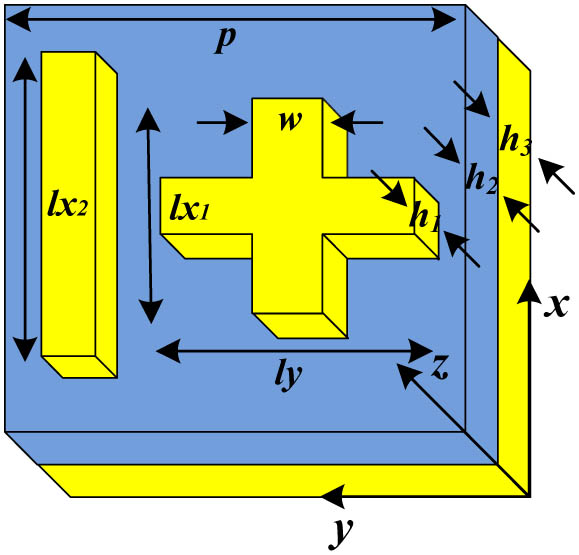
A schematic of the polarization filter cell structure is shown in Fig. 1. This structure can act as a polarization filter that has dual-band filter properties for polarization and single band for polarization. A tunable dual-band filter for both polarizations at the same time is discussed in a subsequent paragraph. As shown in Fig. 1, the top layer is a compound metal nano-structure array comprised of an asymmetrical cross resonator and a rectangle strip which parallels the axis. The asymmetrical cross resonator is formed by two perpendicular rectangle strips which are parallel and vertical to the axis, respectively. The middle and bottom layers are a dielectric spacer and metal film, respectively. The dielectric function of the metal (gold) is given by the Drude model[22]where is the permittivity of the vacuum, the plasma wavelength , is the angle wavelength of the incident wave, and the damping rate . In order to investigate the characteristics of the filter, the reflection spectra are simulated with the 3D FDTD method based on EastFDTD software[23]. In the calculations, the spatial mesh cell is set to and the time step is taken as . The incident wave with polarization propagates along the negative axis. Periodic boundary conditions are set in the - and -directions, and an open boundary is defined in the -direction for the electromagnetic wave incidence and transmission.
Figure 1.Schematic of the polarization filter cell structure. Top layer is a metal compound in rectangular strips. Thickness and the width of the three rectangular strips is and . Middle and bottom layers are and a gold film, respectively. Thicknesses of the layer and gold film are and , respectively. Dimensions of the filter cell structure in both - and -directions are .
Assume that the absorption, reflection, and transmission spectra are , , and , respectively. The absorption can be obtained by . The transmission is zero in the entire investigated wavelength range because that ground plane is metal, thus the absorptivity . When is zero, the structure becomes a perfect absorber. And it is known that the zero is caused by the destructive interference between the direct reflection of an asymmetrical cross resonator array and the subsequent multiple reflections of the dielectric spacer and metal layer[24], and the light is trapped in the dielectric layer[25].
Figure 2 presents the reflection spectra with different light polarizations of a polarization filter as shown in Fig. 1. It is easily found that the reflection spectrum of the polarization has two dips in the wavelength range of interest and the wavelengths of the two dips are 1310 and 2000 nm, respectively. On the other hand, the reflection spectrum of the polarization has one dip which is located at 1516 nm. The reflectivities of the reflection dips are close to zero (0.012 of 1310 nm and 0.052 of 2000 nm for polarization, and 0.003 of 1516 nm for polarization). On the other hand, it is found that the reflectivity of the reflection spectrum corresponding to () at the resonant dip wavelength of the other polarization () is over 0.8. This indicates that the filter has strong polarization selectivity.
Figure 2.Simulated reflection spectra of the filter with , , and for and polarization.
For well-recognized the characters of the resonant dips, the distributions of the electric field of at the surface of metal compound rectangle strips at the wavelengths of the three dips, 1310 and 2000 nm for polarization and 1516 nm for polarization, are depicted in Fig. 3. From Figs. 3(a) and 3(b), we can see that the electric fields at 1310 and 2000 nm for polarization are almost distributed at the edges of the gold rectangle strip and , respectively. There is negligible distribution of the electric field at the vertical gold strip.
Figure 3.Distributions of the electric field at the surface of the metal compound rectangular strips corresponding to the following; polarization at the resonant dip (a) 1310 and (b) 2000 nm; (c) polarization at the resonant dip 1516 nm.
That is to say, the gold strip of the asymmetrical cross resonator vertical to the light polarization has no effect on the resonant wavelength of . From Fig. 3(c), we can observe the similar character at 1516 nm for polarization. The previous discussions reveal a fact that the wavelength of the reflection dip of the filter can be modulated only by changing the parameters of the corresponding gold strip.
On the other hand, it is known that the metal surface charges (SPs) can be deduced from the electric field distribution[26]. So the electric field distribution can present the distribution of the charge oscillation. That is to say, Fig. 3 equivalently indicates the charge oscillation. According to the electric dipole resonance frequency formula[27]where c is the vacuum speed of light, is the charge oscillating length, and is the equivalent permittivity near the metal rectangle strips (where charge exists, the resonant wavelength is proportional to the oscillating length). As shown in Fig. 2, the ratio of , , and is . The ratio of the corresponding resonant wavelength is . It is in accordance with the theory formula. Because the electric field is only distributed at the edges of the gold rectangle strip which caused the resonant effect, and the resonant wavelength is proportional to the length of the corresponding rectangle strip, it opens an accurate and simple way to tune the filtered wavelength freely.
Figure 4(a) presents the reflection spectra of the filter for polarization of the rectangle strips with different length . The values of and are fixed at 450 and 350 nm, respectively. It is found that when increases from 280 to 320 nm with every step of 20 nm, the shorter resonant wavelength for polarization exhibits a redshift; however, the longer resonant wavelength 2000 nm for polarization does not change. By fixing and , and changing from 430 to 470 nm with every step of 20 nm, we can get similar results, as shown in Fig. 4(b).
Figure 4.Simulated reflection spectra of the filter structure as a function of the length; (a) with and is fixed at 450 nm; (b) with and is fixed at 300 nm for polarization.
Moreover, we can change the lengths of and at the same time. When and change from 280 and 430 nm, respectively, to and , respectively, with every step of 20 nm, while is fixed at 350 nm, the reflection spectra of the filter for polarization can be determined (Fig. 5). It is shown that the two resonant wavelengths exhibit a redshift at the same time. The resonant wavelengths are the same with that shown in Fig. 4 while the corresponding rectangular strip has the same length. Meanwhile, the reflection spectra for polarization are shown in Fig. 6. It can be seen that the wavelength of the resonant dip does not change. From Figs. 5 and 6, we can see that the filter wavelength is strongly dependent on the length of the rectangular strips which is in accordance with the light polarization and is independent of the length of the vertical one.
Figure 5.Simulated reflection spectra of the filter structure as a function of the length of the gold strips and with every step of 20 nm at the same time, and is fixed at 350 nm for polarization.
Figure 6.Simulated reflection spectra of the filter structure as a function of the length of the gold strips and with every step of 20 nm at the same time, and is fixed at 350 nm for polarization.
From the previous discussions, we have shown a tunable polarization filter that exhibits a dual-band filter property for polarization and a single band for polarization. Then, a tunable dual-band filter for both polarizations at the same time is realized by using two asymmetrical cross resonators. A schematic cell structure of the dual-band filter is shown in Fig. 7.
Figure 7.Schematic of the dual-band polarization filter cell structure. Top layer is two gold asymmetrical cross resonators. Thickness and the width of the four rectangle strips is and . Middle and bottom layers are and gold films, respectively. Thicknesses of the layer and gold film are and , respectively. Dimensions of the filter cell structure are and along the - and -directions, respectively.
Figure 8 shows the reflection spectra with different light polarizations of the dual-band filter. Moreover, we can change the four resonant wavelengths for both polarizations freely by adjusting the corresponding length of the branch of the asymmetrical resonator at the same time. As shown in Fig. 9, when and change from 280 and 420 nm, to and , with every step of 20 nm, and and are fixed, the two filtered wavelengths corresponding to polarization exhibit a redshift. When and change from 340 and 490 nm, to and , with every step of 20 nm, and and are fixed, the two filtered wavelengths corresponding to polarization exhibit a redshift, as shown in Fig. 10.
Figure 8.Simulated reflection spectra of the filter with , , , and for and polarization.
Figure 9.Simulated reflection spectra of the filter structure as a function of the length of the gold strips and with every step of 20 nm at the same time, while and are fixed at 340 and 490 nm, respectively, for polarization.
Figure 10.Simulated reflection spectra of the filter structure as a function of the length of the gold strips and with every step of 20 nm at the same time, while and are fixed at 300 and 440 nm, respectively, for polarization.
In conclusion, a tunable dual-band infrared polarization filter based on a metal-dielectric-metal compound rectangular strip array is proposed and investigated. First, a polarization filter that possesses dual-band filtering properties for polarization and a single band for polarization is realized. Based on the analysis of the distributions of the electric field at the surface of the metal compound rectangular strips at the filtered wavelength (resonant wavelength), it is found that the resonant wavelength only depends on the length of the rectangular strip which caused the resonant effect. Therefore, the filter wavelength can be tuned freely for different light polarizations by adjusting the length of the corresponding rectangular strip. Second, two asymmetrical cross resonators are used to yield a tunable dual-band filter for both polarizations at the same time. And the calculated results show that the filtered wavelength can be tuned freely. In addition, the calculated results show that all the intensities at the filter wavelengths are closed to zero, which implies that the filter exhibits good filtering performance.