
Jia-Qi Lü, Ping-Ping Li, Dan Wang, Chenghou Tu, Yongnan Li, Hui-Tian Wang. Extending optical filaments with phase-nested laser beams[J]. Photonics Research, 2018, 6(12): 1130
- Photonics Research
- Vol. 6, Issue 12, 1130 (2018)
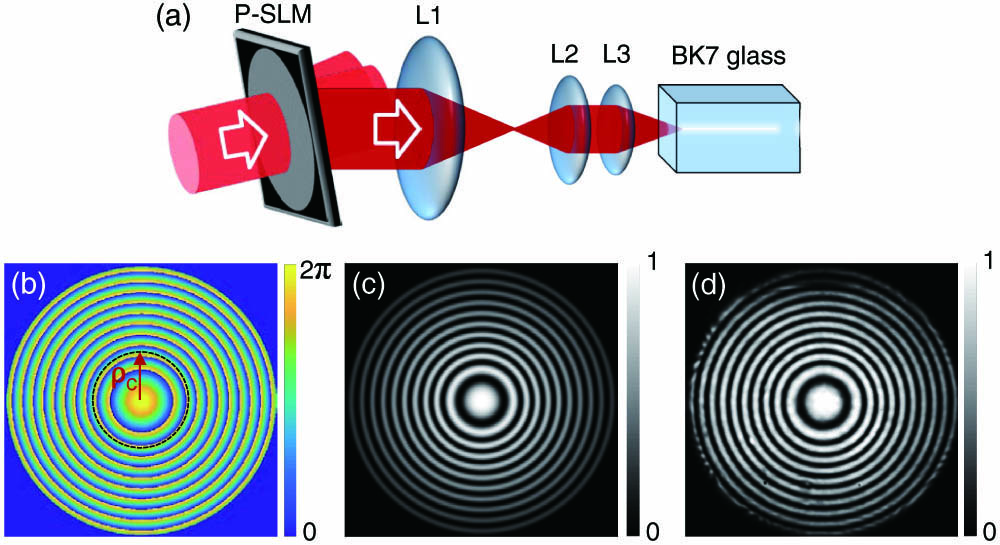
Fig. 1. Generation of a phase-nested beam for prolonging the filament. (a) Experimental setup, (b) phase distribution of the generated phase-nested beam behind lens L3, (c) simulated interference pattern of the phase-nested beam behind lens L3 with the Gaussian beam, and (d) the experimentally measured result corresponding to (c).
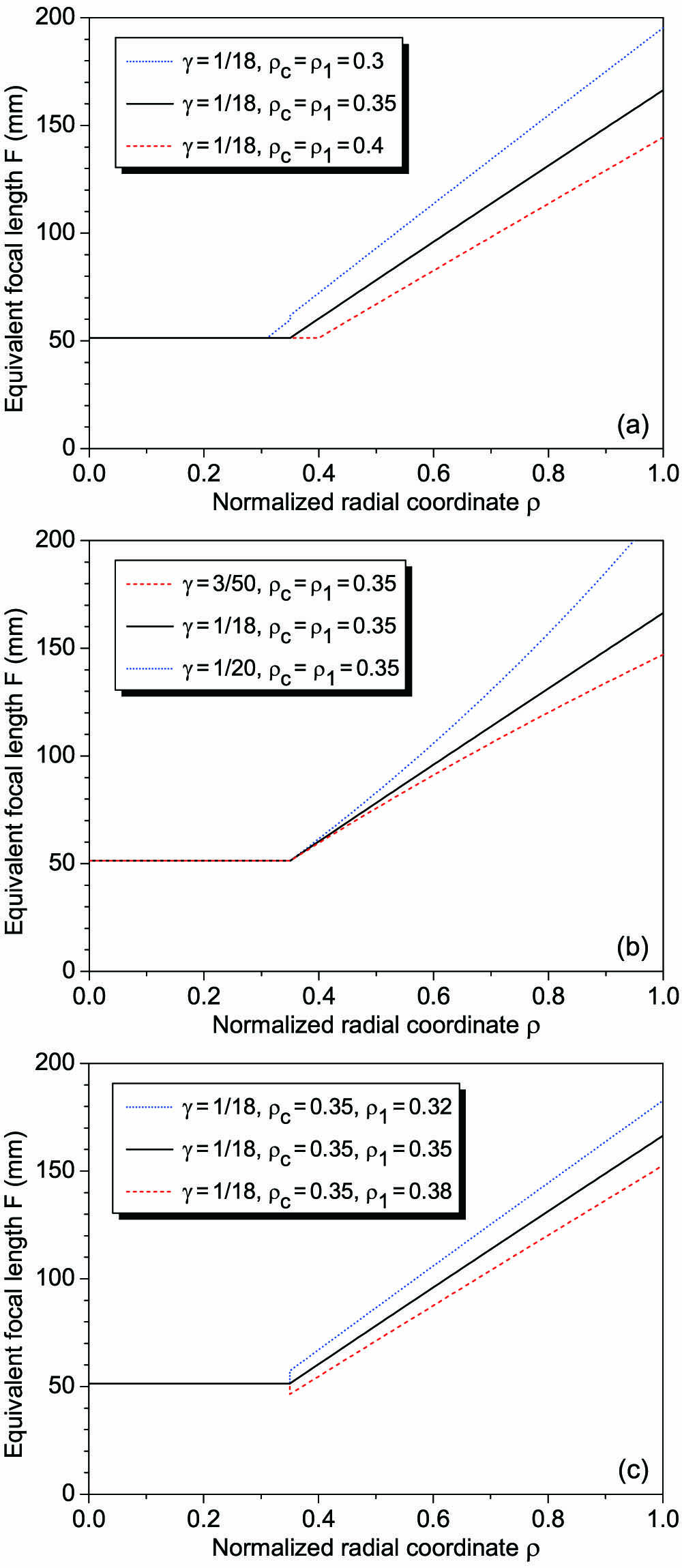
Fig. 2. Equivalent focal length F γ ρ c ρ 1
Fig. 3. Simulated nonlinear propagation behaviors of different beams under the conditions of P = 10 P c ϵ ∼ 10 − 4 f = 0.0125 L d γ = γ 0 ρ c = 0.35 ρ 1 = 0.32 ϕ 0 = 0 ρ ≤ ρ c ρ > ρ c
Fig. 4. Experimental results of the filament extended by the phase-nested beam. (a) Filament produced by the phase-nested beam. (b) Filament produced by the central part of only the phase-nested beam. (c) No filament is formed by the annular part of the phase-nested beam. (d) Filament generated by the Gaussian beam with same pulse energy and beam width as the whole phase-nested beam. The corresponding input beams are shown in the left side, while the corresponding far-field patterns are shown in the right side. (e) The output spectra of the above beams. The ruler is also captured simultaneously as the filaments to measure the filamentation length.
Fig. 5. Filaments produced by the phase-nested beams with different phase shifts. The parameters remain unchanged as r 0 = 1.2 mm γ = 1 / 18 ρ c = 0.35 ρ 1 = 0.32 E = 13 μJ
Fig. 6. Filaments produced by the phase-nested beams with the different parameter sets γ ρ c ρ 1 ϕ 0 E = 13 μJ
Fig. 7. Filaments produced by the partially blocked phase-nested beams. The intensity profiles of the input beams are shown on the left. (a), (c), (e) The filaments produced by the phase-nested beams blocked by a specific ring-like band-stop filter, whose normalized internal radius and width are ρ a d ρ b

Set citation alerts for the article
Please enter your email address
© Copyright 2018-2021 | Chinese Laser Press. All Rights Reserved 沪ICP备15018463号-20