Abstract
Extending the length of femtosecond laser filamentation has always been desired for practical applications. Here, we demonstrate that significant extending of a single filament in BK7 glass can be achieved by constructing phase-nested beams. The filamentation and the following energy replenishment are assembled in a single phase-nested beam. The central part of the phase-nested beam is an apertured Gaussian beam, which is focused into one focal spot to produce a short filament. In contrast, the rest of the annular part converges gradually towards the central axis to continuously replenish the energy for supporting the regeneration of filaments. The common-path generating system ensures the stability of generated filaments and easily optimizes the beam parameters to obtain the longest high-quality filament due to its flexibility. In addition, we discuss the significance of continuous replenishment for extending filaments and the potential for generating more extended filaments based on this method.1. INTRODUCTION
Ultrashort laser filamentation has attracted great attention and been widely used since it was observed for the first time by Braun and his colleagues in 1995 [1]. Light filament acts as a long-range self-guiding propagation process [2] with clamped intensity [3] and self-compression of pulses [4]. It is often accompanied by many specific physical phenomena [5], such as the generation of plasma channels [6], broadband radiation of a supercontinuum [7], and generation of a terahertz (THz) wave [8]. Many applications based on these properties expand the utility of this physical phenomenon [9]. The supercontinuum generation during this self-guiding propagation can be exploited for supervising air pollution based on the technique of multi-component light detection and ranging (LIDAR) [10,11]. The plasma column induced by the high-intensity filaments propagating in gas can be used as triggers and channels for electric discharge, which can then be used as a new type of lightning rod [12–14]. Moreover, the localized intensity of this self-guiding laser pulse can be applied for laser-induced plasma spectroscopy for remote targets [15].
One always seeks generation of the longest filaments because the length has not yet reached the actual requirement, which limits the development of related research and applications. Filamentation requires pulse energy higher than a certain critical value. Properly increasing the energy of laser pulses can prolong the length of the filament to some extent [16]. However, excessively high power density will induce strong absorption and multi-filamentation, which greatly limits the long-range propagation of filaments [17]. Moreover, the energy of the laser pulses cannot be increased without limit. Therefore, a major challenge here is how to make full use of the limited laser energy to produce the filament to be as long as possible. In fact, the key factor for producing the long filament is the background reservoir rather than the intense filament core. The background reservoir, which covers a large area and carries most of the pulse energy but low power density, has been demonstrated to be necessary to maintain the long-range propagation of the filament [18]. The dynamic energy exchange between the reservoir and the filament core plays an important role in extending the filament [19]. Many efforts have been made, and several methods aiming to prolong the filament have been explored. A series of methods is relying on the specific beam modulation to achieve an extending focus distribution along the propagation direction. The Bessel beam [20], Gaussian beam with a stepped wave front [21], annular Gaussian beam [22], and multi-focal-length beam [23] have been demonstrated as effective beam types for generating the prolonged filament without the need of increasing the input energy. Another point of view is to artificially build an external energy supplement for continuously refueling the filament [24]. For example, it has been demonstrated that with the aid of a double path system, a short filament produced by a focused Gaussian beam can be extended by “dressing” an artificially constructed long-range background reservoir, which carries high pulse energy but low power density and will continuously refuel the existing filament. This dressed beam can extend the filament by , compared to that formed by focusing a Gaussian beam with the same pulse energy as the whole dressed beam. In addition, energy exchange between multiple filaments produced by two femtosecond (fs) laser beams with different wavelengths is also a promising approach to remotely replenish and extend filaments [25]. Besides the pure spatial profile modulation, efforts optimizing the temporal profile of the pulses have also been made to achieve longer filaments [26,27].
In this paper, we propose a new scheme to extend the filament. We design and generate phase-nested beams and then demonstrate that the filament produced by the phase-nested beam is much longer than that produced by a Gaussian beam at the same input energy. In our scheme, we directly combine the filamentation and the following refueling into a single phase-nested beam. The central part of the phase-nested beam is focused into a spot to produce a short filament, whereas its annular part gradually converges towards the central axis to form an extended background reservoir. Such a design can effectively ensure the filament to be stably and continuously prolonged. In addition, this scheme has great flexibility, enabling the generation of an optimum filament.
Sign up for Photonics Research TOC. Get the latest issue of Photonics Research delivered right to you!Sign up now
2. GENERATION OF PHASE-NESTED BEAMS
In order to accomplish this design and extend the filament with a phase-nested beam, we propose an experimental setup based on a 4f system composed of paired lenses (L1 and L2), as shown in Fig. 1(a). The input linearly polarized fs Gaussian laser beam from a Ti:sapphire fs regenerative amplifier (Coherent Inc.), with a pulse width of , a repetition frequency of 1 kHz, and a central wavelength of 800 nm, is modulated by a holographic grating (HG) displayed on a phase-only spatial light modulator (P-SLM) with (each pixel has a size of ). The P-SLM and the focusing lens L3 (with a focal length of ) are placed in the input plane (the front focal plane of L1) and the output plane (the rear focal plane of L2) of the 4f system, respectively. The effective modulated area on the P-SLM is a circular area with a diameter of 6 mm (750 pixels), while the other area is blocked. The 4f system compresses the phase-nested beam (with a radius of ) from the P-SLM into the phase-nested beam (with a radius of ) in the output plane of the 4f system.
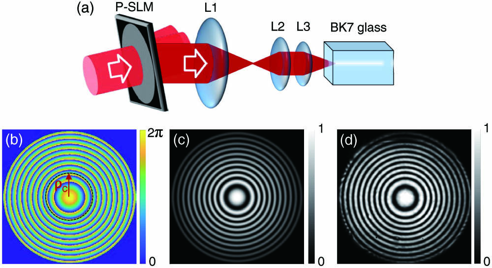
Figure 1.Generation of a phase-nested beam for prolonging the filament. (a) Experimental setup, (b) phase distribution of the generated phase-nested beam behind lens L3, (c) simulated interference pattern of the phase-nested beam behind lens L3 with the Gaussian beam, and (d) the experimentally measured result corresponding to (c).
Because of the simple compression function of the 4f system, to simplify the description, we can use the coordinate system in the output plane of the 4f system to directly describe the transmission function of the HG displayed on the P-SLM as follows: where is the spatial frequency of the HG in the direction, and the additional phase has the form This -oriented HG diffracts the original input Gaussian beam into three orders (0th- and st-orders). We pick out only the st-order beam as the phase-nested beam we need. Such a phase-nested beam on the output plane of the 4f system should be After passing through L3, the phase-nested beam becomes , i.e., Here, we should point out that all the normalized parameters (such as , , , and ) are normalized by , and we use the same normalized polar coordinate on the input and output planes of the 4f system. is the normalized waist radius of the original Gaussian beam, and is the normalized radius of the central part of the phase-nested beam, respectively. We can see from Eq. (3) or (4) that the central part of the beam is completely the same as that of the original input Gaussian beam, while its annular part is modulated by .
The modulation phase is of great importance for producing the phase-nested beam and then for extending the filament. The phase profile has the opposite sign to the focusing lens L3, so it is equivalent to a hollow divergent lens. The parameter in Eq. (2) reflects the focal length of this equivalent divergent lens, which has the ability to cancel the focusing effect of L3. When the equivalent focal length of the modulated divergent lens is equal to that of L3, the parameter is required as . The parameter is used to control the converging behavior of the annular part, and the term ensures the continuity in phase distribution at the boundary of the central and annular parts, which is shown by the red dashed circle in Fig. 1(b). is the adjustable space-invariant phase shift between the central and annular parts. The simulated phase distribution of the phase-nested beam behind L3 is shown in Fig. 1(b) with the parameters , , and , while its intensity distribution always remains a Gaussian profile. To further clarify the phase distribution shown in Fig. 1(b), we simulate the interference pattern between the designed phase-nested beam and the Gaussian beam, which is shown in Fig. 1(c). Figure 1(d) shows the measured interference pattern between the generated phase-nested beam and the Gaussian beam. Clearly, the perfect consistency between Figs. 1(c) and 1(d) confirms that the phase distribution of the generated phase-nested beam is indeed what we desired.
In our experiment, L3 focuses the phase-nested beam into the BK7 glass (), whose input plane has a distance of 23 mm from L3. The change of the equivalent focus as a function of the normalized radial coordinate for different parameters , , and is shown in Fig. 2. The equivalent focal length is the realistic distance between L3 and the focus when considering the arrangement of BK7 glass. A continuous change of focus can be obtained when , as shown in Figs. 2(a) and 2(b). However, as shown in Fig. 2(c), if , a jump appears in the focus distribution, while if , the focus exhibits a local overlapping. Uniform focus distribution, which means a straight line in Fig. 2, occurs only when . If , there is a compressed covering focus region, while will lead to a stretched focus region.

Figure 2.Equivalent focal length of the phase-nested beam for different , , and in BK7 glass, as a function of the normalized radial coordinate.
3. NONLINEAR PROPAGATION BEHAVIOR OF PHASE-NESTED BEAMS
To theoretically explore the nonlinear propagation behavior of the phase-nested beam in a nonlinear BK7 glass, the nonlinear wave equation should be used. Under the slowly varying amplitude approximation and the assumption that the temporal profile of the pulses remains unchanged, a simplified model can be expressed as [28] where is the propagation distance normalized by the diffraction length of the beam with a radius of . represents the space-variant complex amplitude normalized by the total field. The second term on the right side of Eq. (5) acts as a saturable Kerr nonlinearity [5,29,30]. The parameter describes the relative relationship between the third- and fifth-order Kerr nonlinearities. denotes the input power, and is the critical power for the self-focusing [31]. The last term of Eq. (5) stands for the multi-photon absorption (MPA) effect, which acts as an energy loss, where is the -photon absorption coefficient. The BK7 glass has a critical power of for the self-focusing of the 800 nm fs laser [32]. For the BK7 glass, its band gap of [33] should correspond to a three-photon () absorption of the 800 nm laser.
Simulated nonlinear propagating behaviors of different beams are shown in Fig. 3 when taking , , , , , , and . Figures 3(a)–3(d) show the simulation results of normalized on-axis intensities as a function of propagation distance. Figures 3(e)–3(h) show the cross-section intensity distributions corresponding to Figs. 3(a)–3(d), respectively. Clearly, the phase-nested beam can indeed greatly extend the filament shown in Figs. 3(a) and 3(e), compared with the Gaussian beam shown in Figs. 3(d) and 3(h), without changing the input energy. As shown in Figs. 3(b) and 3(f), the central part () of the phase-nested beam exhibits a steep peak around the focal plane of L3, indicating the formation of a short filament. As shown in Figs. 3(c) and 3(g), the annular part () of the phase-nested beam propagates at low power density, and there is no steep peak in this case. As the central and annular parts are assembled into a phase-nested beam, several steep peaks appear in the on-axis intensity evolution shown in Fig. 3(a). This result is beyond the simple addition of Figs. 3(b) and 3(c) and actually reflects the process that the annular part continually replenishes the existing filament and supports the regeneration of filamentation.
Figure 3.Simulated nonlinear propagation behaviors of different beams under the conditions of , , , , , , and . Simulated on-axis intensity of nonlinear propagation of (a) the whole phase-nested beam, (b) the central part () of the phase-nested beam, (c) the annular part () of the phase-nested beam, and (d) the Gaussian beam with the same input power and size as the phase-nested beam. (e)–(h) show the intensity in cross-sections as a function of propagation distance corresponding to (a)–(d), respectively.
4. EXPERIMENTAL RESULTS
Figure 4 shows the experimental results of the input beam profiles, the produced filament profiles, and the far-field patterns. The bright lines of the filament profiles originate from the scattered light of supercontinuum radiation accompanied with the filamentation. In Fig. 4(a), the phase-nested beam (with the pulse energy of and parameters , , , , ) produces a long filament with a length of . In Fig. 4(b), a filament of is produced only by the central part ( and the pulse energy is ) of the phase-nested beam. In Fig. 4(c), the annular part () of the phase-nested beam carries most of the pulse energy () but cannot form an observable filament. In Fig. 4(d), the filament of is generated by the Gaussian beam at the same pulse energy () and the beam width as the whole phase-nested beam. The corresponding input beams are shown in the left side. Comparing Fig. 4(d) with Fig. 4(a), we find that the phase-nested beam makes the filament achieve an extension of without increasing the input energy. The corresponding far-field patterns are shown on the right side of Fig. 4, while the output spectra are recorded by using a spectrometer (Ocean Optics USB4000, covering a spectrum region of 200–1100 nm) in Fig. 4(e).
Figure 4.Experimental results of the filament extended by the phase-nested beam. (a) Filament produced by the phase-nested beam. (b) Filament produced by the central part of only the phase-nested beam. (c) No filament is formed by the annular part of the phase-nested beam. (d) Filament generated by the Gaussian beam with same pulse energy and beam width as the whole phase-nested beam. The corresponding input beams are shown in the left side, while the corresponding far-field patterns are shown in the right side. (e) The output spectra of the above beams. The ruler is also captured simultaneously as the filaments to measure the filamentation length.
Obviously, a single peak can be observed in the far-field patterns of Figs. 4(a) and 4(b), indicating a stable single filament. In contrast, the far-field pattern of the Gaussian beam presents several peaks and a disordered profile, as shown in Fig. 4(d), meaning that multiple filaments are produced [21]. Different from other cases, the far-field pattern in Fig. 4(c) exhibits a ring profile originating from the diffraction of the annular part. In particular, the output spectrum of the annular part is almost the same as that of the original laser. Both the filament and the far-field pattern are captured by a digital camera (Nikon, D7000) with an exposure time of 20 s in Figs. 4(a)–4(c) and 1 s in Fig. 4(d) for the filaments, while there is an exposure time of 1.3 s for the far-field patterns [21]. One should point out that the breakdown threshold of the BK7 glass is [34], which is higher than the power density in the experiment within a range of , but we still strictly limit the illuminating time under the intense laser to avoid the permanent damage to BK7. Clearly, the simulation results in Fig. 3 and the experimental results in Fig. 4 prove the reasonability and validity of our idea. In particular, the phase-nested beam can effectively suppress the generation of multiple filaments.
In order to determine the influence of the parameters in Eq. (3) on the filament produced by the phase-nested beam, we implement experiments under different parameter sets. Although between the central and annular parts has no effect on the focus distribution of the phase-nested beam, the quality of the filament is sensitive to . The filaments produced by the phase-nested beams with different are shown in Fig. 5, while the other parameters remain unchanged as , , , , and . The length and uniformity of the filament exhibit a great difference with the change of . When the phase shift is within a range of in Figs. 5(b)–5(e), the filaments exhibit the relatively long and uniform profiles. When the phase shift reaches , meaning that the central and annular parts are out of phase, the extending effect almost disappears. The extending is also not ideal when the phase shift is within a range of . These phenomena are also universal for the other sets of parameters.
Figure 5.Filaments produced by the phase-nested beams with different phase shifts. The parameters remain unchanged as , , , , and . The exposure time of the digital camera stays at 20 s.
The dependence of the filament on the parameters of , , , and is shown in Fig. 6. Based on the experimental results in Fig. 5, is limited within a range of to obtain the high-quality filament. The extending effects can be observed for all of the parameter sets, but the extending lengths are also quite different. More extended focus distribution of the phase-nested beam does not always lead to a longer filament, as shown in Fig. 6. The parameters affect the maximum length and quality of the filament simultaneously. Since the parameters can be adjusted continuously, it is possible to find the longest and high-quality filament under a finite input power by finding the optimal parameters set.
Figure 6.Filaments produced by the phase-nested beams with the different parameter sets , , , and . The pulse energy of all of the input fields is kept at , and the exposure time of the digital camera stays at 20 s.
5. DISCUSSION
As mentioned above, the central part with relatively high power density but low pulse energy produces the filamentation around its focal position, while the annular part with high pulse energy but low power density does not lead to the filamentation when it is incident into the medium alone. As the central and annular parts are assembled into one phase-nested beam, the annular part will continually replenish the existing filament and support the regeneration of the filament.
We further implement the investigation on the continuous replenishment behavior during the filamentation. The annular part is partially and completely blocked in a specific radial region, introducing the perturbation to the energy replenishment. The experimental results are shown in Fig. 7. The left side of Fig. 7 shows the intensity distribution of the input phase-nested beam with the parameters of , , , , and . We will explore two types of intensity modulation. In Figs. 7(a), 7(c), and 7(e), the phase-nested beams are blocked by a specific ring-like band-stop filter, which is defined by the internal radius of and the ring width of . In Figs. 7(b), 7(d), and 7(f), the phase-nested beams are blocked by a low-passing circular aperture with a radius of . The parameters , , and are also normalized by . Clearly, the filaments produced for the two types of intensity modulation are almost the same for the situation of . Despite only a little attenuation of power induced by the ring-like band-stop filter, the results show that only the central part (), which seems to be isolated, is the effective part to produce the filament. Even if the continuity of energy replenishment is destroyed locally, the propagation of filaments will be cut off immediately. This also means that to achieve a long and high-quality filament, one needs to ensure the continuity of energy replenishment. In addition, it is not difficult to find that the increase of or leads to the extending of the filament, indicating that a longer filament can be achieved when the effective replenishment extends to a longer range.
Figure 7.Filaments produced by the partially blocked phase-nested beams. The intensity profiles of the input beams are shown on the left. (a), (c), (e) The filaments produced by the phase-nested beams blocked by a specific ring-like band-stop filter, whose normalized internal radius and width are and , respectively. (b), (d), (f) The filaments produced by the phase-nested beams blocked by a low-passing circular aperture with a normalized radius of .
The input power/energy is greatly limited by the damage threshold of the P-SLM, so if the damage threshold can be greatly raised or a specifically designed phase plate can be fabricated to directly achieve the phase-nested beam, it can be predicted to achieve a greatly extended filament even in air [24].
6. CONCLUSION
In conclusion, a extension of the filament has been achieved in the BK7 glass by using the phase-nested beam, with respect to the traditional Gaussian beam without increasing the input power. Multiple filamentation is effectively suppressed with the aid of the phase-nested structure. The central part of the phase-nested beam is an apertured Gaussian beam, which is focused into one focal spot to produce a short filament. In contrast, the rest of the annular part converges gradually towards the central axis, acting as the continuous replenishment for supporting the regeneration of filaments. In our idea, the filamentation and energy replenishment are assembled in a single phase-nested beam simultaneously, which greatly promotes the stability and simplification of the whole system. In addition, the flexibility of this method provides the possibility of searching for the proper modulation parameters to achieve a long and uniform single filament. Finally, we discuss the significance of continuous replenishment for extending the filament.
References
[1] A. Braun, G. Korn, X. Liu, D. Du, J. Squier, G. Mourou. Self-channeling of high-peak-power femtosecond laser pulses in air. Opt. Lett., 20, 73-75(1995).
[2] G. Méchain, C. D’Amico, Y. B. André, S. Tzortzakis, M. Franco, B. Prade, A. Mysyrowicz, A. Couairon, E. Salmon, R. Sauerbrey. Range of plasma filaments created in air by a multi-terawatt femtosecond laser. Opt. Commun., 247, 171-180(2005).
[3] J. Kasparian, R. Sauerbrey, S. L. Chin. The critical laser intensity of self-guided light filaments in air. App. Phys. B, 71, 877-879(2000).
[4] A. Couairon, J. Biegert, C. P. Hauri, W. Kornelis, F. W. Helbing, U. Keller, A. Mysyrowicz. Self-compression of ultra-short laser pulses down to one optical cycle by filamentation. J. Mod. Opt., 53, 75-85(2006).
[5] A. Couairon, A. Mysyrowicz. Femtosecond filamentation in transparent media. Phys. Rep., 441, 47-189(2007).
[6] H. Yang, J. Zhang, W. Yu, Y. J. Li, Z. Y. Wei. Long plasma channels generated by femtosecond laser pulses. Phys. Rev. E, 65, 016406(2001).
[7] D. Aumiler, T. Ban, G. Pichler. Femtosecond laser-induced cone emission in dense cesium vapor. Phys. Rev. A, 71, 063803(2005).
[8] C. D’Amico, A. Houard, M. Franco, B. Prade, A. Mysyrowicz, A. Couairon, V. T. Tikhonchuk. Conical forward THz emission from femtosecond-laser-beam filamentation in air. Phys. Rev. Lett., 98, 235002(2007).
[9] J. Kasparian, M. Rodriguez, G. Méjean, J. Yu, E. Salmon, H. Wille, R. Bourayou, S. Frey, Y. B. André, A. Mysyrowicz, R. Sauerbrey, J. P. Wolf, L. Wöste. White-light filaments for atmospheric analysis. Science, 301, 61-64(2003).
[10] J. Yu, D. Mondelain, G. Ange, R. Volk, S. Niedermeier, J. P. Wolf, J. Kasparian, R. Sauerbrey. Backward supercontinuum emission from a filament generated by ultrashort laser pulses in air. Opt. Lett., 26, 533-535(2001).
[11] G. Méjean, J. Kasparian, J. Yu, S. Frey, E. Salmon, J. P. Wolf. Remote detection and identification of biological aerosols using a femtosecond terawatt lidar system. Appl. Phys. B, 78, 535-537(2004).
[12] X. M. Zhao, J. C. Diels, C. Y. Wang, J. M. Elizondo. Femtosecond ultraviolet laser pulse induced lightning discharges in gases. IEEE J. Quantum Electron., 31, 599-612(1995).
[13] M. Rodriguez, R. Sauerbrey, H. Wille, L. Wöste, T. Fujii, Y. B. André, A. Mysyrowicz, L. Klingbeil, K. Rethmeier, W. Kalkner, J. Kasparian, E. Salmon, J. Yu, J. P. Wolf. Triggering and guiding megavolt discharges by use of laser-induced ionized filaments. Opt. Lett., 27, 772-774(2002).
[14] D. Comtois, H. Pepin, F. Vidal, F. A. M. Rizk, C.-Y. Chien, T. W. Johnston, J. C. Kieffer, B. L. Fontaine, F. Martin, C. Potvin, P. Couture, H. P. Mercure, A. Bondiou-Clergerie, P. Lalande, I. Gallimberti. Triggering and guiding of an upward positive leader from a ground rod with an ultrashort laser pulse. I. Experimental results. IEEE Trans. Plasma Sci., 31, 377-386(2003).
[15] P. Rohwetter, J. Yu, G. Méjean, K. Stelmaszczyk, E. Salmon, J. Kasparian, J. P. Wolf, L. Wöste. Remote LIBS with ultrashort pulses: characteristics in picosecond and femtosecond regimes. J. Anal. At. Spectrom., 19, 437-444(2004).
[16] X. D. Sun, T. Zeng, H. Gao, S. W. Zhang, W. W. Liu. Power dependent filamentation of a femtosecond laser pulse in air by focusing with an axicon. J. Phys. B, 48, 094004(2015).
[17] M. Mlejnek, M. Kolesik, J. Moloney, E. Wright. Optically turbulent femtosecond light guide in air. Phys. Rev. Lett., 83, 2938-2941(1999).
[18] W. Liu, F. Théberge, E. Arévalo, J. F. Gravel, A. Becker, S. L. Chin. Experiment and simulations on the energy reservoir effect in femtosecond light filaments. Opt. Lett., 30, 2602-2604(2005).
[19] W. Liu, J. F. Gravel, F. Théberge, A. Becker, S. L. Chin. Background reservoir: its crucial role for long-distance propagation of femtosecond laser pulses in air. Appl. Phys. B, 80, 857-860(2005).
[20] P. Polynkin, M. Kolesik, A. Roberts, D. Faccio, P. Di Trapani, J. Moloney. Generation of extended plasma channels in air using femtosecond Bessel beams. Opt. Express, 16, 15733-15740(2008).
[21] Y. Fu, H. Xiong, H. Xu, J. Yao, B. Zeng, W. Chu, Y. Cheng, Z. Xu, W. Liu, S. L. Chin. Generation of extended filaments of femtosecond pulses in air by use of a single-step phase plate. Opt. Lett., 34, 3752-3754(2009).
[22] Z. F. Feng, W. Li, C. X. Yu, X. Liu, J. Liu, L. B. Fu. Extended laser filamentation in air generated by femtosecond annular Gaussian beams. Phys. Rev. A, 91, 033839(2015).
[23] Z. F. Hong, Q. B. Zhang, S. Ali Rezvani, P. F. Lan, P. X. Lu. Extending plasma channel of filamentation with a multi-focal-length beam. Opt. Express, 24, 4029-4041(2016).
[24] M. Scheller, M. S. Mills, M. A. Miri, W. Cheng, J. V. Moloney, M. Kolesik, P. Polynkin, D. N. Christodoulides. Externally refuelled optical filaments. Nat. Photonics, 8, 297-301(2014).
[25] Y. Liu, M. Durand, S. Chen, A. Houard, B. Prade, B. Forestier, A. Mysyrowicz. Energy exchange between femtosecond laser filaments in air. Phys. Rev. Lett., 105, 055003(2010).
[26] S. Tzortzakis, G. Méchain, G. Patalano, M. Franco, B. Prade, A. Mysyrowicz. Concatenation of plasma filaments created in air by femtosecond infrared laser pulses. Appl. Phys. B, 76, 609-612(2003).
[27] L. Bergé. Boosted propagation of femtosecond filaments in air by double-pulse combination. Phys. Rev. E, 69, 065601(2004).
[28] N. Aközbek, C. M. Bowden, A. Talebpour, S. L. Chin. Femtosecond pulse propagation in air: variational analysis. Phys. Rev. E, 61, 4540-4549(2000).
[29] A. Couairon. Dynamics of femtosecond filamentation from saturation of self-focusing laser pulses. Phys. Rev. A., 68, 015801(2003).
[30] M. Centurion, Y. Pu, M. Tsang, D. Psaltis. Dynamics of filament formation in a Kerr medium. Phys. Rev. A, 71, 063811(2005).
[31] S. M. Li, Z. C. Ren, L. J. Kong, S. X. Qian, C. H. Tu, Y. N. Li, H. T. Wang. Unveiling stability of multiple filamentation caused by axial symmetry breaking of polarization. Photon. Res., 4, B29-B34(2016).
[32] J. K. Ranka, R. W. Schirmer, A. L. Gaeta. Observation of pulse splitting in nonlinear dispersive media. Phys. Rev. Lett., 77, 3783-3786(1996).
[33] A. Horn, E. W. Kreutz, R. Poprawe. Ultrafast time-resolved photography of femtosecond laser induced modifications in BK7 glass and fused silica. Appl. Phys. A, 79, 923-925(2004).
[34] J. W. Jeon, S. Y. Ji, H. Y. Kim, W. Choi, Y. G. Shin, S. H. Cho. Formation of permanent brown-colored patterns in transparent BK7 glass upon irradiation with a tightly focused femtosecond laser. Res. Rev. J. Mater. Sci., 6, 35-38(2018).


