
Y. X. Wang, S. M. Weng, P. Li, Z. C. Shen, X. Y. Jiang, J. Huang, X. L. Zhu, H. H. Ma, X. B. Zhang, X. F. Li, Z. M. Sheng, J. Zhang. Depolarization of intense laser beams by dynamic plasma density gratings[J]. High Power Laser Science and Engineering, 2023, 11(3): 03000e37
- High Power Laser Science and Engineering
- Vol. 11, Issue 3, 03000e37 (2023)
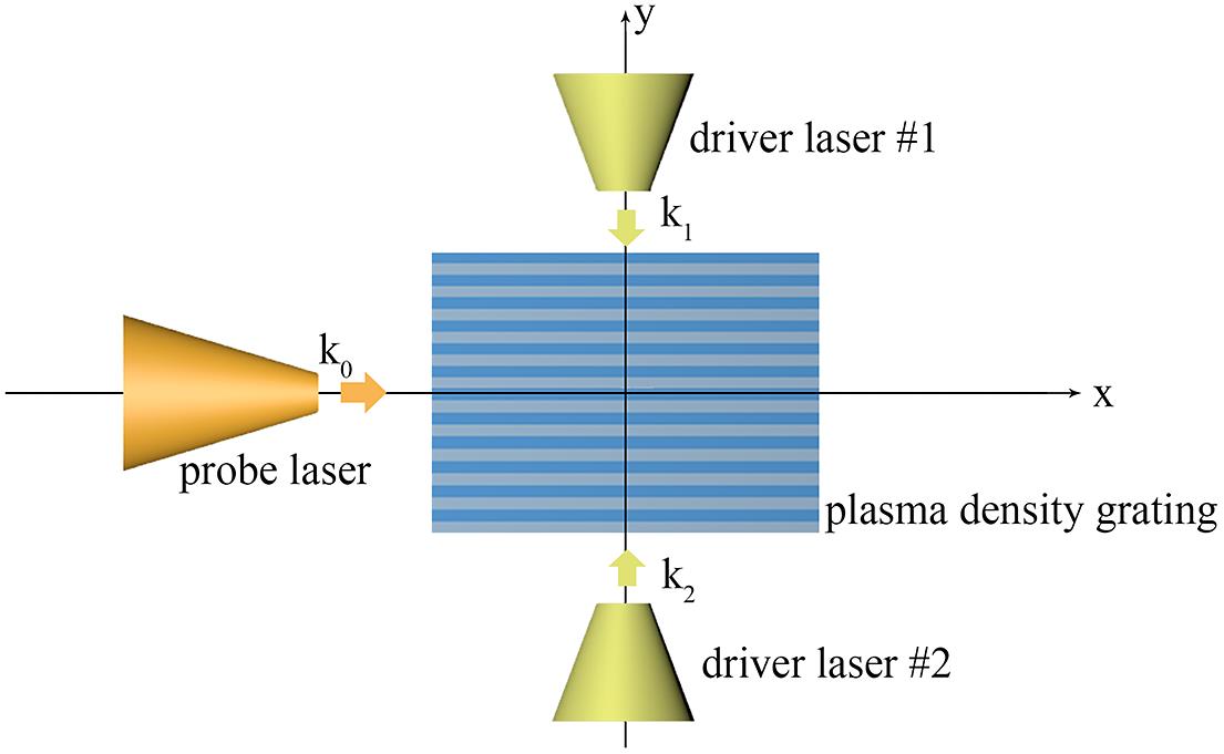
Fig. 1. Schematic of laser depolarization by a PDG. The PDG driven by intersecting laser pulses #1 and #2 will be nonuniform in the  direction and also time-dependent. After the probe laser pulse passes through such a PDG, its polarization state will become nonuniform and time-dependent.
direction and also time-dependent. After the probe laser pulse passes through such a PDG, its polarization state will become nonuniform and time-dependent. 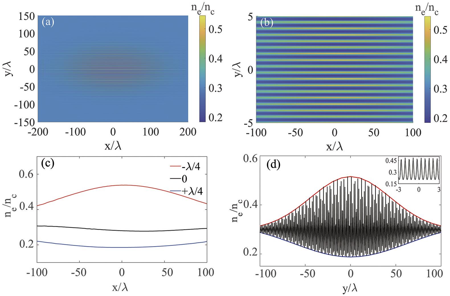
Fig. 2. The electron density distribution of (a) the overall plasma region and (b) the center region  at
at  , respectively. (c) The corresponding electron density profiles along the
 x direction at  , respectively. Here,
  are roughly along the plasma density trough and peak, respectively. (d) The corresponding electron density profiles along the
  direction at
  , in which the inset displays the enlarged density profile in the region
  . The upper and lower envelopes of this density profile are also outlined by the red and blue curves, respectively.
at , respectively. (c) The corresponding electron density profiles along the , respectively. Here, are roughly along the plasma density trough and peak, respectively. (d) The corresponding electron density profiles along the direction at , in which the inset displays the enlarged density profile in the region . The upper and lower envelopes of this density profile are also outlined by the red and blue curves, respectively. Fig. 3. The time evolution of the electron density profile along the  -axis. Note that the PDG experiences a time periodic process of formation, saturation and collapse. The simulation parameters are the same as those in
 Figure 2 .
-axis. Note that the PDG experiences a time periodic process of formation, saturation and collapse. The simulation parameters are the same as those in Fig. 4. The phase velocities of the s-polarized ( ) and p-polarized (
 ) light waves obtained from Equations (
4 ) and (5 ), respectively, in which the electron density profile presented in Figure 2(d) is employed.
) and p-polarized () light waves obtained from Equations (Fig. 5. The spatial distributions of the Stoke parameters (a)  , (b)
, (b)  , (c)
, (c)  and (d)
  of the probe laser pulse at
  after it passes through the PDG. Here, all Stokes parameters are normalized to the instantaneous maximum laser intensity
  . The simulation parameters are given in the text.
, (b) , (c) and (d) of the probe laser pulse at after it passes through the PDG. Here, all Stokes parameters are normalized to the instantaneous maximum laser intensity . The simulation parameters are given in the text. Fig. 6. (a) Longitudinal profiles of the Stokes parameters at  and (b) transverse profiles of the Stokes parameters at
  . (c) Longitudinally averaged polarization degree
  and (d) transversely averaged polarization degree
  . The simulation parameters are the same as those in
 Figure 5 .
and (b) transverse profiles of the Stokes parameters at . (c) Longitudinally averaged polarization degree and (d) transversely averaged polarization degree . The simulation parameters are the same as those in Fig. 7. Laser depolarization by the PDG that is induced by two intersecting laser pulses with an intersection angle  .
.
. Fig. 8. The spatial distributions of the Stoke parameters (a) I , (b) Q , (c) U and (d) V of the probe laser pulse at  after it passes through the PDG that is induced by two intersecting laser pulses with an intersection angle
  . Here, all Stokes parameters are normalized to the instantaneous maximum laser intensity
  . The simulation parameters are given in the text.
after it passes through the PDG that is induced by two intersecting laser pulses with an intersection angle . Here, all Stokes parameters are normalized to the instantaneous maximum laser intensity . The simulation parameters are given in the text. Fig. 9. (a) Longitudinal profiles of the Stokes parameters at y = 0 and (b) transverse profiles of the Stokes parameters at  . (c) Longitudinally averaged polarization degree
  and (d) transversely averaged polarization degree
  . The simulation parameters are the same as those in
 Figure 8 .
. (c) Longitudinally averaged polarization degree and (d) transversely averaged polarization degree . The simulation parameters are the same as those in Fig. 10. The saturation time  (black solid lines) and the maximal achievable ion density
  (red solid lines) as functions of (a) the laser intensity
  for a given initial plasma density
  and (b) the initial plasma density
  for a given laser intensity
  . Except for the laser intensities and initial plasma densities, other laser–plasma parameters are the same as those used in
 Figure 5 .
(black solid lines) and the maximal achievable ion density (red solid lines) as functions of (a) the laser intensity for a given initial plasma density and (b) the initial plasma density for a given laser intensity . Except for the laser intensities and initial plasma densities, other laser–plasma parameters are the same as those used in 
Set citation alerts for the article
Please enter your email address
© Copyright 2018-2021 | Chinese Laser Press. All Rights Reserved 沪ICP备15018463号-20