
Xiao Wang, Shijie Tu, Xin Liu, Yuehan Zhao, Cuifang Kuang, Xu Liu, Xiang Hao. Advance and Prospect for Three-Dimensional Super-Resolution Microscopy[J]. Laser & Optoelectronics Progress, 2021, 58(22): 2200001
- Laser & Optoelectronics Progress
- Vol. 58, Issue 22, 2200001 (2021)
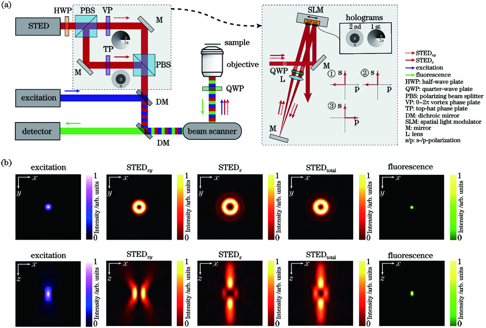
Fig. 1. Principle for 3D-STED nanoscopy based on a single-objective geometry. (a) Simplified schematic of the optical setup; (b) results of PSF
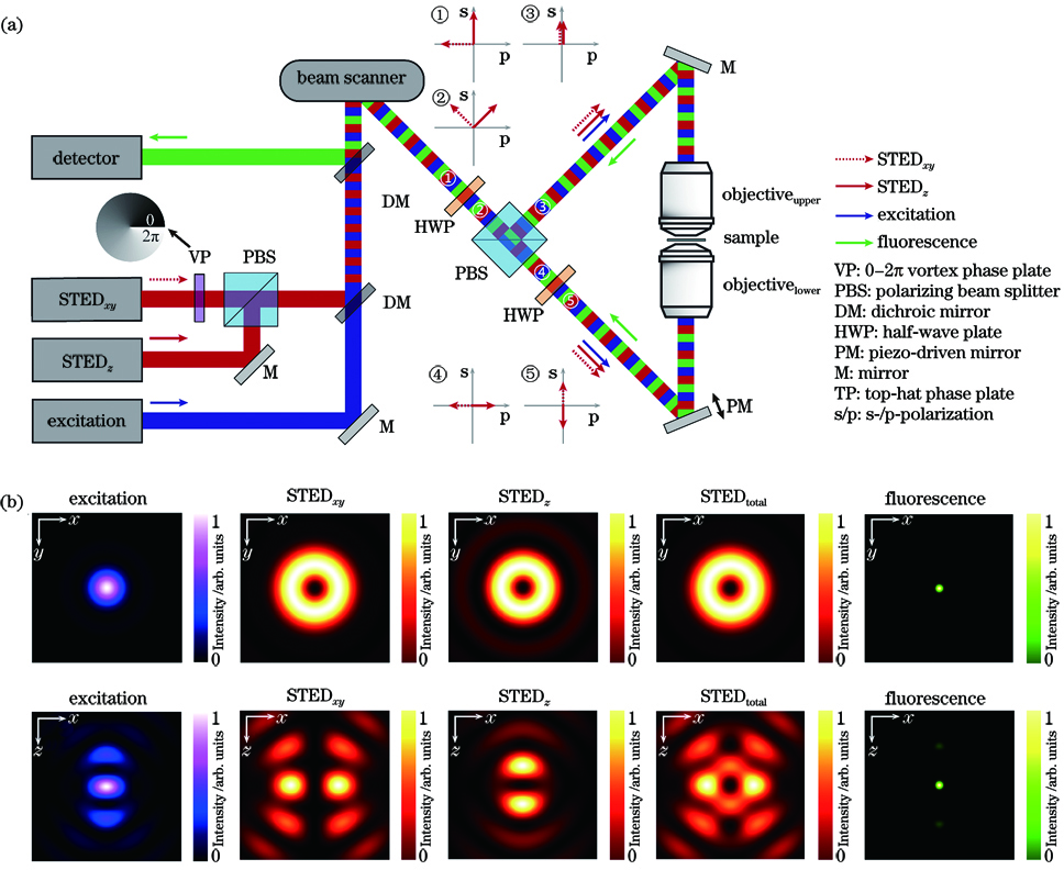
Fig. 2. Principle of isoSTED nanoscopy based on a dual-objective geometry. (a) Simplified schematic of the optical setup; (b) results of PSF
Fig. 3. Images of aberration-free PSF at different axial positions[53]
Fig. 4. Schematic of 3D STORM[55]. (a) Experimental setup; (b) calibration curves of image widths wx and wy as functions of z; (c) three-dimensional localization distribution of single molecule
Fig. 5. Schematic of DH-PSF system and z-calibration[64]. (a) Experimental setup; (b) angle between two main lobes and horizontal direction varying with z; (c) imaging results of a fluorescent bead at different axial positions using calibration curve
Fig. 7. Schematics of dMUM and MUM systems[84]
Fig. 8. Imgaing by using distorted diffraction grating and lens[89]. (a) Single object is imaged onto multiple image planes; (b) multiple objects are imaged onto a single image plane
Fig. 9. Schematic of MFM system[91]
Fig. 10. Schematic of 3D imaging principle of pyramidal micromirror holes[100]. (a) Orthogonal tracking principle in vertical motion; (b) SEM image of pyramidal micromirror holes; (c) orthogonal tracking principle in general condition; (d) a series of images from orthogonal tracking movie of 190 nm diameter particle in water/glycerine solution
Fig. 11. Schematic of VVSRM system[101]
Fig. 12. Schematic of mirror 3D imaging[103]
Fig. 13. Schematic of SMLFM system[97]. (a) Experimental setup; (b) microlens array samples spatial and angular information from the wavefront, which exhibits asymmetric curvature of the primary image plane; (c) simulated point spread functions for two different light field microscopes
Fig. 14. Schematic of SAF[106]. (a) Emission angular distributions of UAF and SAF of fluorophore close to interface; (b) SAF intensity decreases exponentially with increasing surface distance z
Fig. 15. Principles of 3D-SAFM[112]. (a) Radiant flux for angle θ from the optical axis of a fluorophore with randomized orientation at different distances z from a water-glass interface; (b) experimental setup; (c) simulated relationship between distance z from a water-glass interface and relative detection efficiencies of SAF and UAF; (d) enlarged view of optical path
Fig. 16. Schematic of DAISY system[113]
Fig. 17. Schematic of dSALM system[106]. (a) Experimental setup; (b) UAF and SAF channels seen on the camera with the Bertrand lens (BL) inserted in the optical path (upper panel) and without the Bertrand lens (BL) inserted in the optical path (lower panel)
Fig. 19. Schematic of iPALM system[123]. (a) Experimental setup; (b) two beams emitted from a fluorophore with z-position δ interfere in a special 3-channel beam splitter; (c) amplitude distribution detected by camera in each channel, and the phase difference between two adjacent channels is 120°
Fig. 20. Schematic of W-4PiSMSN system[121]

Set citation alerts for the article
Please enter your email address
© Copyright 2018-2021 | Chinese Laser Press. All Rights Reserved 沪ICP备15018463号-20