
Sijie Zhu, Zhoujie Wu, Jing Zhang, Qican Zhang, Yajun Wang. Superfast and large-depth-range sinusoidal fringe generation for multi-dimensional information sensing[J]. Photonics Research, 2022, 10(11): 2590
- Photonics Research
- Vol. 10, Issue 11, 2590 (2022)
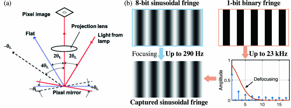
Fig. 1. (a) DMD working mode. (b) Conventional 8-bit sinusoidal fringe focusing projection and 1-bit binary defocusing principle.
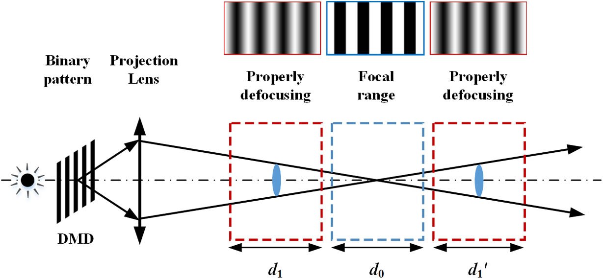
Fig. 2. Limitation of depth range for binary defocusing fringe projection.
Fig. 3. Multifocal optical projection system model.
Fig. 4. Proposed oblique projection method. (a) Simulation results of binary defocusing fringe patterns at different oblique projection angles and different depths. (b) Anisotropic filtering effects and the spectral distribution of binary fringe.
Fig. 5. Square binary method and the OPWM method. (a) Quarter-wave symmetric OPWM waveform. (b) Squared binary pattern. (c) OPWM pattern. (d), (e) Corresponding spectra of (b), (c).
Fig. 6. Experimental setup.
Fig. 7. Fringe sinusoidality in large depth range. (a) Phase RMS errors at different depths for different cases. (b)–(d) Fringe patterns captured in the focal range, intensity of a row of the corresponding fringe pattern, and corresponding spectrum, respectively [corresponding to I NS I WS I WO
Fig. 8. Accuracy analysis and comparison of the proposed method. (a) 3D reconstructed results. (b) 3D reconstructed result of the WL OPWM at Z 3
Fig. 9. Zoom-in 3D plots and cross sections of typical 4D reconstruction results for complex dynamic statues in large depth range (Visualization 1 ).
Fig. 10. Measuring the motion process of multiple pendulums. (a) 4D reconstruction at three moments (Visualization 2 ). (b) Poly-pendulum shape at corresponding moment.
Fig. 11. 4D reconstruction results of superfast shooting of paper cups (Visualization 3 ).
Fig. 12. Measured results of the deformed tennis ball. (a) Captured temporal overlapping encoding (3 + 1 Visualization 4 ). (c) Retrieved texture maps at corresponding moments. (d)–(f) Strain maps (E x x E x y E y y

Set citation alerts for the article
Please enter your email address
© Copyright 2018-2021 | Chinese Laser Press. All Rights Reserved 沪ICP备15018463号-20