
Sijie Zhu, Zhoujie Wu, Jing Zhang, Qican Zhang, Yajun Wang. Superfast and large-depth-range sinusoidal fringe generation for multi-dimensional information sensing[J]. Photonics Research, 2022, 10(11): 2590
- Photonics Research
- Vol. 10, Issue 11, 2590 (2022)
Abstract
1. INTRODUCTION
High-speed and large-depth-range multi-dimensional information sensing has gained popularity and captured the imagination of the public as well as researchers in many fields. With recent interests, the sensing technology is continuously required to be faster, deeper, and more accurate to a wide application spectrum. For example, the demand for time-varying three-dimensional (3D) shapes and corresponding strain information has increased significantly in fields such as biological recognition [1], intelligent manufacturing [2], and materials mechanics analysis [3]. Among many optical sensing and measuring methods such as single-pixel imaging (SPI), structured-illumination microscopy (SIM), spatial frequency domain imaging (SFDI), and fringe projection profilometry (FPP) [4–8], sinusoidal fringe is general and demonstrates unique advantages. The purpose of the ideal sinusoidal fringe is either to provide frequency information or to extract the underlying phase, providing us with multi-dimensional information sensing of the real world.
With the rapid development of digital projection technology, sinusoidal fringes can be easily generated and controlled using the digital micromirror device (DMD) [9]. Typically, the projection rate of 8-bit sinusoidal fringe patterns is closed to 200 Hz. However, each micromirror on the DMD can be independently tilted to either or from its surface normal to generate binary patterns at up to tens of kilohertz. To utilize this mechanism, researchers proposed the binary defocusing technique by generating quasi-sinusoidal profiles with 1-bit binary patterns through a lens defocusing effect [10]. Despite the speed breakthrough, the technique works well only within a limited depth range, in which the binary fringes can be properly defocused into sinusoidal ones.
To enlarge the measurement depth range and improve the accuracy of the binary defocusing technique, various optimization algorithms have been explored, which can be divided into three major categories. The first is to modulate a conventional square binary pattern in spatial domain [11–18], so that a smaller defocusing effect is required and the working depth range can be enhanced to a certain extent. The second is to convert the input square binary fringes into sinusoidal ones by emulating the defocusing process based on deep-learning networks, but it requires the collection of large-scale samples to construct the training dataset [19]. The third is defocusing degree controlling approaches [20,21], which quantify the projection defocusing degree and then optimize the system parameters to ensure good sinusoidal distribution. Even though the fringe quality is guaranteed, the working depth range is not actually expanded.
Sign up for Photonics Research TOC. Get the latest issue of Photonics Research delivered right to you!Sign up now
Though the abovementioned optimization algorithms are effective to enhance the depth range to a certain extent, none of them can overcome its essential limitation caused by the focal plane of the conventional projection system. In 2020, Jiang
To this end, in this paper, we propose a multifocal projection system and oblique projection method to realize superfast and large-depth-range sinusoidal fringe generation for multi-dimensional information sensing. First, by introducing a cylindrical lens, we establish a multifocal projection system based on an off-the-shelf optical projector, which can be modeled as an anisotropic Gaussian filter. Second, under the proposed multifocal system, we found that with various oblique angles of the cylindrical lens, the defocusing effect of binary patterns is totally different in a large depth range. When the angle is set about 45°, the anisotropic filtering effect can perfectly keep fundamental frequency components while eliminating high-order harmonics of the binary structure. On this basis, to achieve a better high-frequency suppression effect, we further optimized the square binary pattern using the optimal pulse width modulation (OPWM) method. Through the aforementioned steps, we finally completely overcome the limitation of the focal range of the conventional method and greatly enhance the depth range of sinusoidal fringe generation. Furthermore, combined with an efficient high-speed measurement algorithm, superfast and large-depth-range multi-dimensional information sensing can be realized. Experiments simultaneously achieve sinusoidal fringe generation with high speed (9524 fps; fps, frames per second) and large depth range (560 mm, about three times that of the conventional method), and multi-dimensional information [such as , , , ; (strain)] sensing.
2. METHODS
A. Limitation of Superfast Binary Defocusing
Among many multi-dimensional information sensing methods, 8-bit sinusoidal fringes are usually used as coding patterns. The DMD is an ideal choice for generating sinusoidal fringes due to its superior ability of easy control and fast modulation through optical switching (“on” and “off”), as shown in Fig. 1(a). However, 8-bit patterns through the DMD have a limited maximum projection rate of 290 Hz (e.g., model V-7001, ViALUX). In contrast, using 1-bit binary patterns, the maximum projection speed is increased up to 23 kHz, which is improved by 80 times. To overcome the speed limitation, the binary defocusing technique was developed by utilizing 1-bit binary patterns and generating pseudo sinusoidal patterns with projector lens defocusing effects [10], as shown in Fig. 1(b). So far, this technology has demonstrated the nonnegligible potential in many fields [23,24]. For example, in the field of FPP, it is successfully applied in challenging scenarios such as the 3D reconstruction of live rabbit hearts and the shooting process of flying bullets [25,26]; for SFDI, the binary defocusing technique enabled the first demonstration of quantitative optical properties of strongly turbid media with a speed of kilohertz such as an
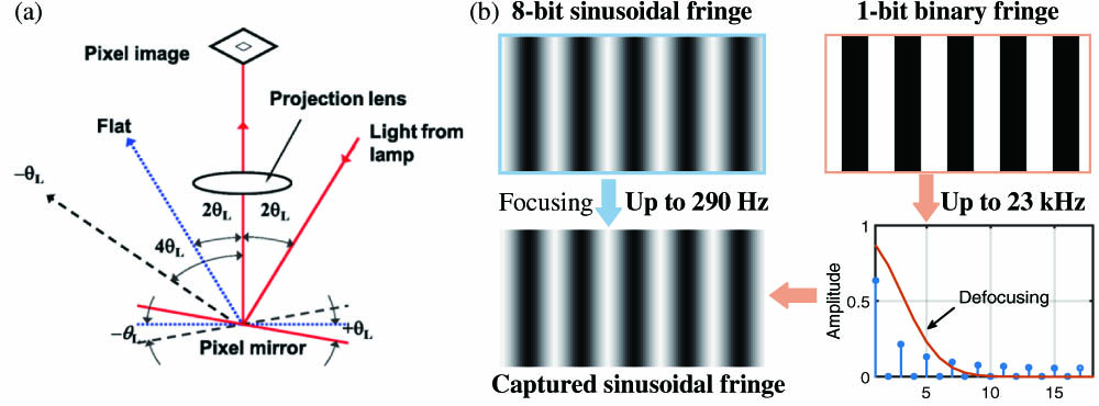
Figure 1.(a) DMD working mode. (b) Conventional 8-bit sinusoidal fringe focusing projection and 1-bit binary defocusing principle.
The intensity distribution of a square binary pattern can be mathematically formulated as follows:
This equation incorporates an infinite sum of cosine waves, the first-order harmonic of which indicates the ideal sinusoidal fringe. The undesired high-order harmonics would deteriorate the sinusoidality of fringes, which could be effectively alleviated by a proper defocusing effect. The defocusing blur of the projector lens can be considered as a low-pass Gaussian filter. The modulation of a Gaussian function is as follows:
However, due to the inherent characteristics of the conventional projection system, the binary defocusing technique requires the projector to be properly adjusted within a small out-of-focus range for high-accuracy measurements, limiting its depth measurement capability. As shown in Fig. 2, the conventional axial symmetrical projection system has a single focal plane, and the depth range can be divided into two types of regions: focal range and properly defocusing range or . Only in properly defocusing region or can the defocusing effect be modeled as a suitable Gaussian low-pass filter generating approximate sinusoidal fringes; in contrast, in focal region , the binary fringe pattern does not work well. But for sensing occasions, especially dynamic scenes, the limited working depth range or cannot meet the actual demand.
![]()
Figure 2.Limitation of depth range for binary defocusing fringe projection.
B. Multifocal Projection System and Oblique Projection Method
Conventional systems have restricted working depth ranges due to the existence of a single focal plane. To solve this problem, we propose a multifocal projection system and oblique projection method. The principle of the multifocal optical projection system is illustrated in Fig. 3. Different from the conventional axial symmetrical projection system, the proposed system has multiple focal planes, and the focal planes for different axes are separated in the depth dimension by introducing a cylindrical lens.
![]()
Figure 3.Multifocal optical projection system model.
The proposed multifocal system can be modeled by an anisotropic Gaussian filter. When the cylindrical lens does not rotate (), its point spread function can be described by the anisotropic Gaussian distribution in Eq. (3). When the cylindrical lens is rotated by an angle relative to the world coordinate system, the anisotropic filtering model is shown in Eq. (4) and Eq. (5):
On the basis of the multifocal projection system, we found that by changing the rotation angle of the cylindrical lens from the axis to axis or the oblique angle of fringes, the binary fringes have different defocusing effects in the whole depth range. However, with the proposed multifocal system, if the conventional orthogonal projection is used, there will still be the limitation of depth range due to the focal plane along the or axis. To this end, we propose an optimal oblique projection method. This method optimally adjusts the rotation angle of the cylindrical lens or oblique angle of fringes, the former changing the shape of the anisotropic filter while the latter modulating the spectral distribution of a binary fringe, which can effectively filter out high-order harmonics and give the fringes good sinusoidal characteristics.
To better illustrate the oblique projection method, we carried out corresponding simulation experiments. In the proposed multifocal system, with different oblique angles (0°, 45°, 90°), the defocusing distribution of binary patterns is shown in Fig. 4(a). We can see that the focal range is unavoidable when binary patterns are projected vertically or horizontally; but when the angle is set at about 45°, the binary pattern can be properly defocused in the depth range, thus overcoming the problem of the focal plane. The reason is that when adjusting the oblique angle of the fringe, the spectral distribution will be modulated accordingly, as shown in Fig. 4(b). One may find that at , the direction is defocused, and the direction is focused, which is an anisotropic elliptical filter effect; at , both and directions are properly defocusing, which is a uniform filtering effect; at , there is an opposite filtering effect to that at . The anisotropic filtering effect of the multifocal system at different depths can keep fundamental frequency components of 45° binary fringes, so as to realize the generation of sinusoidal fringes in a large depth range. The same effect can be achieved by setting the rotated angle of the cylindrical lens to about 45°, which is adopted in this paper.
![]()
Figure 4.Proposed oblique projection method. (a) Simulation results of binary defocusing fringe patterns at different oblique projection angles and different depths. (b) Anisotropic filtering effects and the spectral distribution of binary fringe.
C. OPWM Method for Eliminating Specific Harmonics
The multifocal system and oblique projection method eliminate the single focal plane and high-order harmonics. To achieve better performance, we further adopt the OPWM method to selectively eliminate undesired frequency components by inserting different types of notches in a conventional binary square wave [14], as shown in Fig. 5(a).
![]()
Figure 5.Square binary method and the OPWM method. (a) Quarter-wave symmetric OPWM waveform. (b) Squared binary pattern. (c) OPWM pattern. (d), (e) Corresponding spectra of (b), (c).
Figure 5(b) shows one squared binary pattern, and Fig. 5(d) demonstrates its spectrum distribution containing third, fifth, seventh,…, odd-order harmonic frequencies. Figure 5(c) illustrates an OPWM pattern. For a periodic waveform, because of the half-cycle symmetry of the OPWM wave, the Fourier series coefficients , , and can be simplified as
For the binary OPWM waveform, , we have
By optimally adjusting the notch positions, selected harmonics can be eliminated. For instance, if the three-step phase-shifting algorithm is adopted, triplen harmonics will not influence the phase error. Thus, to eliminate fifth-, seventh-, and 11th-order harmonics, as shown in Fig. 5(e), two notches can be set, and the following equations can be formulated:
3. EXPERIMENTS
We tested the proposed method under the scenario of FPP. As shown in Fig. 6, our system consisted of a high-speed digital-light-processing (DLP) projector (DLP VisionFly 6500) with a resolution of pixels, a cylindrical lens (effective focal length of 700 mm, size of ) attached to the projector at an angle of about 45°, and a high-speed CCD camera (Photron FASTCAM Mini AX200) with a 16 mm lens. The camera resolution was set as pixels, and the camera was synchronized by a trigger signal from a projector. The projector illuminated test objects with pre-designed binary patterns, and the camera captured 8-bit grayscale images simultaneously from a different perspective. With this system, we employed an efficient and robust gray-code-based algorithm to update an absolute phase map using only four newly captured patterns (three sinusoidal and one gray-code patterns) [27]. Finally, a simple calibration method based on a reference plane was applied to convert the absolute phase into height information for 3D reconstruction [28].
![]()
Figure 6.Experimental setup.
A. Comparative Analysis of Phase Error in Large Depth Range
We first conducted experiments by utilizing a white board to verify the effectiveness of the proposed method and evaluate the phase error over the entire measurable depth range of our experimental setup. The original depth (0 mm) is set at in Fig. 3, and the focal plane of the conventional projection system is at from the original position. For each depth position, the phase root-mean-square (RMS) errors are obtained by comparing the phase calculated by the 42-step and three-step phase-shifting algorithms for fringe patterns with fringe period pixels. Depths with phase errors less than 0.02 rad are considered effective depth. We compared the defocusing effect and phase quality in a large depth range for the following three cases: only square binary fringes projected without the cylindrical lens (labeled as NL Square), and square binary fringes (labeled as WL Square) and OPWM patterns (labeled as WL OPWM) adopted after introducing the cylindrical lens.
From the phase RMS error distribution in Fig. 7(a), the resulting curve of NL Square has an obvious parabolic profile, and it shows low phase errors only in a limited depth range (about 188 mm). For the WL Square, the depth range (about 545 mm) and phase quality are significantly improved. Furthermore, the results of WL OPWM demonstrate superior quality with a large depth range of not less than 560 mm, and its phase error curve is very stable. Specifically, near the focal plane of the conventional projection system, fringe presents obvious binary distribution, and the high-order harmonic component is still very significant, as shown in Fig. 7(b), while fringes and have good sinusoidality, as shown in Figs. 7(c) and 7(d). It is worth noting that the 45° cylindrical lens will change the focal length of the original system. Thus, instead of comparing under the same reference depth, we compared the respective results at the focal plane before and after introducing the cylindrical lens. However, since the focal plane is eliminated after applying the proposed method, depth in Fig. 3 is selected for the latter two groups for comparison. Therefore, the proposed method eliminates high-order harmonics and the single focal plane of the conventional axisymmetric projection system, and then two separated properly defocusing regions can be connected, thereby significantly increasing the measurable depth (about three times that of the conventional method), which demonstrates the effectiveness of the proposed method.
![]()
Figure 7.Fringe sinusoidality in large depth range. (a) Phase RMS errors at different depths for different cases. (b)–(d) Fringe patterns captured in the focal range, intensity of a row of the corresponding fringe pattern, and corresponding spectrum, respectively [corresponding to
B. Accuracy Analysis of 3D Reconstruction
To quantitatively evaluate and compare the accuracy of the proposed method, a designed step-shaped workpiece was respectively measured in the above three cases and at the , , and positions in Fig. 3, with a depth range of approximately 465 mm. The step height of the workpiece is 30 mm, and the machining error is less than 30 μm. The 3D reconstruction results are shown in Fig. 8(a), and Fig. 8(b) displays the result of the WL OPWM at . First, with the proposed multifocal system, all positions present ideal reconstruction results, but the result of NL Square is good only at , and dense ripples appear due to insufficient defocusing. The flatness and accuracy in the axis of the measured planes in each step were evaluated, and the cross-sectional error distribution of each plane is shown in Fig. 8(c). The RMS errors (curve graph, axis shown on the left) and the mean of height (bar graph, axis shown on the right) are shown in Fig. 8(d). We can see that the RMS errors of NL Square gradually decrease from the focal range to the properly defocusing region; for the results of WL Square, the measurement errors are significantly reduced and stable in the whole depth range; the RMS errors of the WL OPWM are further reduced with all less than 0.15 mm, and the minimum is 0.0265 mm. In addition, the average RMS errors in the whole depth range of the three cases are respectively 0.3758 mm, 0.1377 mm, and 0.0840 mm, verifying that the proposed method can measure the 3D shape of objects with consistently high precision in a large depth range.
![]()
Figure 8.Accuracy analysis and comparison of the proposed method. (a) 3D reconstructed results. (b) 3D reconstructed result of the WL OPWM at
C. 4D Information Sensing on Complex Dynamic Scenes
All objects are in absolute motion, so for most optical systems, it is not enough to study just the static 3D shape. For moving objects or dynamic scenes, it is also necessary to demonstrate the effectiveness of dynamic measurement for the proposed method, that is, the information sensing capability in 4D (, , , ) space.
1. Performance Comparison of Moving Objects in Large Depth Range
The first dynamic experiment was carried out to compare the performance between the conventional and proposed methods in a dynamic scene in a large depth range. The two isolated statues translated in the depth direction were reconstructed in the above three cases, with a translation depth of about 420 mm, and the focal range is roughly around 75 mm. The complete 4D sensing results of this translation process are provided in
![]()
Figure 9.Zoom-in 3D plots and cross sections of typical 4D reconstruction results for complex dynamic statues in large depth range (
2. Superfast Dynamic Scene Sensing in Large Depth Range
Further, the second group of dynamic experiments test the speed performance of the proposed method in two superfast scenes with complex surfaces at a 4D reconstruction rate of . In the first scene, the regularly swinging process for multiple pendulums was measured. The poly-pendulum includes many shiny and reflective balls, so we sprayed white developer on their surfaces to avoid high-dynamic-range (HDR) problems. It should be noted that the HDR effect can also be eliminated by other methods [29]. Figure 10(a) shows the reconstructed 3D frame at three representative moments. To further analyze the motion law, the trajectories formed by all pendulums were obtained by tracking the center of the ball, as shown in Fig. 10(b). The swing amplitude increased gradually, and the “S” shape became more obvious over time. Results indicate that the swinging multiple pendulums in a large depth range can be efficiently reconstructed at a high-speed rate, which can be applied to explore the motion law in physical experiments. The whole 4D reconstructed process is provided in
![]()
Figure 10.Measuring the motion process of multiple pendulums. (a) 4D reconstruction at three moments (
![]()
Figure 11.4D reconstruction results of superfast shooting of paper cups (
D. Multi-dimensional Information Sensing for Strain Analysis
In addition to the abovementioned static 3D and dynamic 4D scenes, practical applications also involve the need of strain () for structural or material mechanics analysis, which requires multi-dimensional (, , , , ) information sensing. Therefore, combining our recently proposed digital image correlation (DIC) assisted FPP method [30], multi-dimensional measurement in a large depth range can be achieved. A dynamic scene is analyzed to test the validity of this combining method, during which a tennis ball was thrown onto a tennis racket and then squeezed and deformed. The specific analysis steps are as follows.
Step 1: The binary patterns and gray-coded patterns were projected and synchronously captured using the time-overlapping coding strategy, as shown in Fig. 12(a).
![]()
Figure 12.Measured results of the deformed tennis ball. (a) Captured temporal overlapping encoding (
Step 2: For every four patterns we obtain, a new 3D shape result can be restored by the temporal phase unwrapping technique and system calibration. Figure 12(b) shows the 3D reconstructed shapes at different moments, and the reconstructed rate of our system is .
Step 3: The high-quality texture images are separated by calculating the modulation of three phase-shifting sinusoidal patterns; the corresponding texture images are shown in Fig. 12(c).
Step 4: 2D image matching and tracking were executed using DIC, and the 3D coordinate matching was achieved using the 3D shape and 2D matching information. Here, for a given point in the reference image, the widely used zero-mean normalized cross correlation (ZNCC) is used as a correlation criterion to determine the position and shape of the subset in the deformed image by maximizing a correlation coefficient.
Step 5: The strain in the region of interest (ROI) was calculated by subtracting the 3D coordinates and differencing the matching point as shown in Figs. 12(d)–12(f). The Green–Lagrangian strain is adopted in this work for strain analysis [31].
By analyzing the strain , , and , it can be seen that the tennis ball was in the free fall stage (71.40 ms) at the beginning, and no deformation occurred, so the strain was almost zero. From the moment of touching on the racket (73.92 ms) with slight deformation to the moment with maximum extrusion (79.80 ms), the strain gradually increased. Then the tennis ball rotated (82.32 ms), and the strain also changed with this rotation to release the internal force. Finally, it rebounded upwards (84.84 ms), and the strain gradually decreased. Experimental results show that the proposed superfast and large-depth-range method can simultaneously achieve 4D shape measurement and strain analysis for a dynamic scene, that is, sensing multi-dimensional information.
4. CONCLUSION
In this work, we have presented a superfast and large-depth-range sinusoidal fringe generation method and realized multi-dimensional information sensing. We first propose the multifocal optical system and oblique projection method, essentially to overcome the limitation of a single focal plane in conventional axisymmetric systems and suppress high-order harmonics of square binary fringes in the large depth range. Then, the OPWM method is introduced to eliminate specific harmonics and preserve fundamental frequency components. Experimental results have verified that binary fringes can be converted into high-quality sinusoidal fringes in a large depth range, and through measuring standard step-height objects, the reconstructed accuracy is much better than that of conventional methods. It can achieve efficient and robust multi-dimensional information sensing of regular and random moving objects, and strain analysis in a large depth range. Compared with existing methods, the proposed method stands out in the following aspects.
It is worth noting that the final sinusoidal characteristics are closely related to the fringe period and parameters of the multifocal system, and thus both should be carefully chosen to achieve the best performance, which will be further explored in later research. Due to the advantages of the proposed method, we believe it may provide new insights into the development of high-speed, high-precision, and large-depth-range optical metrology such as SPI, SFDI, FPP, and SIM.

Set citation alerts for the article
Please enter your email address
© Copyright 2018-2021 | Chinese Laser Press. All Rights Reserved 沪ICP备15018463号-20