
Dong Pan, Zaisheng Lin, Jiawei Wu, Haoran Zhang, Zhen Sun, Dong Ruan, Liuguo Yin, Gui Lu Long. Experimental free-space quantum secure direct communication and its security analysis[J]. Photonics Research, 2020, 8(9): 1522
- Photonics Research
- Vol. 8, Issue 9, 1522 (2020)
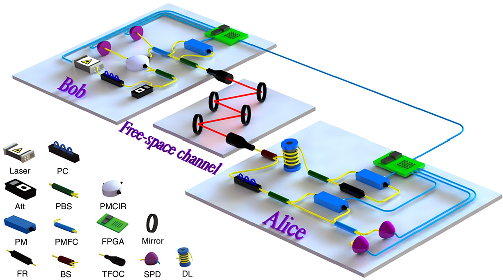
Fig. 1. Schematic diagram of free-space QSDC system. Att, attenuator; BS, beam splitter; DL, delay line; FPGA, field-programmable gate array; FR, Faraday rotator; PBS, polarization beam splitter; PC, polarization controller; PM, phase modulator; PMCIR, polarization-maintaining circulator; PMFC, polarization-maintaining fiber coupler; SPD, single-photon detector; TFOC, triplet fiber-optic collimator. Blue, yellow, and red lines are the electric line, optical fiber line, and free-space path, respectively.
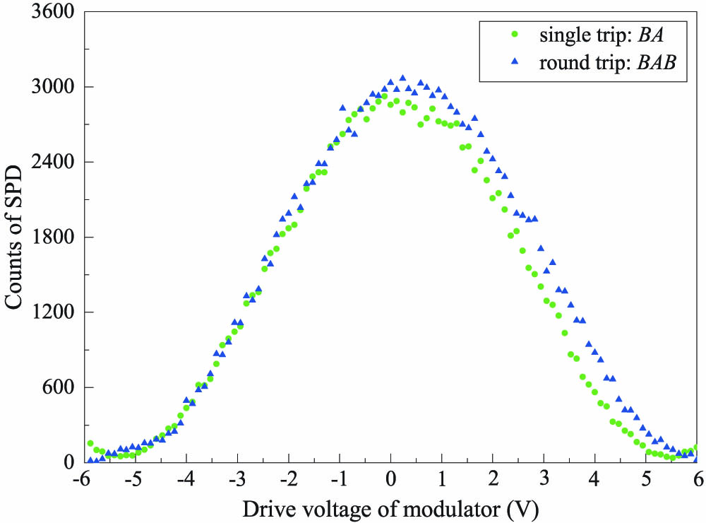
Fig. 2. Interference fringes. Driving voltage ranges from − 6 V + 6 V
Fig. 3. Error rates during image file transmission. Dashed lines represent the mean values of DBER, and dash-dotted lines show the mean values of QBER. The definition of DBER and QBER is given in Section 2.A , while the experimental approach for accessing them is introduced in Section 2.B .
Fig. 4. Illustration of Eve’s attack strategies. n E μ BA Q μ BA e det BA ρ BE Q μ BAE ρ BAE E μ BAB Q μ BAB e det BAB
Fig. 5. Secrecy capacities versus the attenuation given the collective attack as well as the PNS and USD attack under the framework of GLLP analysis. The curves labeled by different markers represent the data with different mean photon numbers.
Fig. 6. Comparison of the secrecy capacities calculated by the GLLP theory and the decoy-state method. Simulations in the decoy-state method using μ = 0.1 ν 1 = 0.07 ν 2 = 0.0445 ν 3 = 0.03 μ = 0.1 C s , 1 + 2 C s , 1

Set citation alerts for the article
Please enter your email address
© Copyright 2018-2021 | Chinese Laser Press. All Rights Reserved 沪ICP备15018463号-20