• Chinese Optics Letters
  • Vol. 18, Issue 12, 120501 (2020)
Jie Sheng, Jianlan Xie, and Jianjun Liu*
Author Affiliations
  • Key Laboratory for Micro/Nano Optoelectronic Devices of Ministry of Education & Hunan Provincial Key Laboratory of Low-Dimensional Structural Physics and Devices, School of Physics and Electronics, Hunan University, Changsha 410082, China
  • show less
    DOI: 10.3788/COL202018.120501 Cite this Article Set citation alerts
    Jie Sheng, Jianlan Xie, Jianjun Liu. Multiple super-resolution imaging in the second band of gradient lattice spacing photonic crystal flat lens[J]. Chinese Optics Letters, 2020, 18(12): 120501 Copy Citation Text show less
    (a) Model of the GPC flat lens. The lattice spacing ayi (the subscript i takes the value from 1 to 19) is decreased along the positive and negative directions of the Y axis; the lattice spacing ax is a, and it stays the same along the X direction. (b) Half of the structure surrounded by the rectangular area with the blue dashed line in (a).
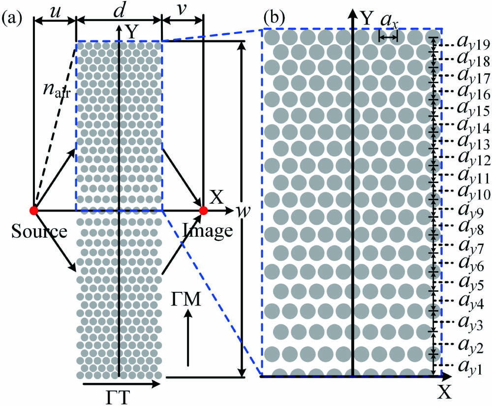
    Fig. 1. (a) Model of the GPC flat lens. The lattice spacing ayi (the subscript i takes the value from 1 to 19) is decreased along the positive and negative directions of the Y axis; the lattice spacing ax is a, and it stays the same along the X direction. (b) Half of the structure surrounded by the rectangular area with the blue dashed line in (a).
    vg1(a) Unit cell of the triangular lattice PC and the unit cell modified by lattice spacing ayi in real space. The WS primitive cells are surrounded by red lines. (b) The band structure of the WS primitive cell modified by lattice spacing ay1. Inset is the first Brillouin zone, and the area around the letters is the irreducible Brillouin zone. The light cone is marked by the blue dotted line. (c) Analysis of the direction of beam propagation by EFCs. vg1 and vg2, are negative and positive refractions, respectively[45].
    Fig. 2. vg1(a) Unit cell of the triangular lattice PC and the unit cell modified by lattice spacing ayi in real space. The WS primitive cells are surrounded by red lines. (b) The band structure of the WS primitive cell modified by lattice spacing ay1. Inset is the first Brillouin zone, and the area around the letters is the irreducible Brillouin zone. The light cone is marked by the blue dotted line. (c) Analysis of the direction of beam propagation by EFCs. vg1 and vg2, are negative and positive refractions, respectively[45].
    EFCs of the second band affected by lattice spacings at the wavelength of 3.122 μm.
    Fig. 3. EFCs of the second band affected by lattice spacings at the wavelength of 3.122 μm.
    EFCs of the second bands of WS primitive cells modified by lattice spacing ay1 (red curves, corresponding to α=6°) and ay3 (blue curves, corresponding to γ=27.4°) at specific wavelengths: (a) λ1, (b) λ2, and (c) λ3. The black dashed circles are the light cones. The black arrows represent wave vectors (kair) in the air, and the red and blue arrows represent group velocities (vg1). (d) The variation of NERI with ayi at the wavelengths of λ1, λ2, and λ3.
    Fig. 4. EFCs of the second bands of WS primitive cells modified by lattice spacing ay1 (red curves, corresponding to α=6°) and ay3 (blue curves, corresponding to γ=27.4°) at specific wavelengths: (a) λ1, (b) λ2, and (c) λ3. The black dashed circles are the light cones. The black arrows represent wave vectors (kair) in the air, and the red and blue arrows represent group velocities (vg1). (d) The variation of NERI with ayi at the wavelengths of λ1, λ2, and λ3.
    Imaging fields of the PC and GPC flat lenses for the point source at specific wavelengths. PC: (a) λ1, (b) λ2, (c) λ3; GPC: (d) λ1, (e) λ2, (f) λ3.
    Fig. 5. Imaging fields of the PC and GPC flat lenses for the point source at specific wavelengths. PC: (a) λ1, (b) λ2, (c) λ3; GPC: (d) λ1, (e) λ2, (f) λ3.
    Magnitudes of the axial plane of imaging fields: (a) λ1, (b) λ2, (c) λ3. Magnitudes of the image plane of imaging fields: (d) λ1, (e) λ2, (f) λ3.
    Fig. 6. Magnitudes of the axial plane of imaging fields: (a) λ1, (b) λ2, (c) λ3. Magnitudes of the image plane of imaging fields: (d) λ1, (e) λ2, (f) λ3.
    Off-axis point source imaging of the GPC flat lens at a wavelength of 3.231 μm.
    Fig. 7. Off-axis point source imaging of the GPC flat lens at a wavelength of 3.231 μm.
    (a) GPC plano-concave lens model. (b) Focus field of the GPC plano-concave lens for the plane wave.
    Fig. 8. (a) GPC plano-concave lens model. (b) Focus field of the GPC plano-concave lens for the plane wave.
    Number of Scatterers on the X AxisFWHM of PC Flat LensFWHM of GPC Flat Lens
    λ1λ2λ3λ1λ2λ3
    5/0.38/0.440.560.64
    70.520.41/0.400.490.66
    90.520.560.620.420.440.48
    11/0.37/0.460.470.50
    13///0.480.610.61
    Table 1. The FWHM of Image Points Under the Different Thicknesses of GPC and PC Flat Lenses at Wavelengths λ1, λ2, and λ3
    Jie Sheng, Jianlan Xie, Jianjun Liu. Multiple super-resolution imaging in the second band of gradient lattice spacing photonic crystal flat lens[J]. Chinese Optics Letters, 2020, 18(12): 120501
    Download Citation