Abstract
Based on the triangular lattice two-dimensional photonic crystal (PC), the lattice spacing along the transverse direction to propagation is altered, and a gradient PC (GPC) flat lens is designed. The band structures and equal frequency curves of the GPC are calculated; then, the imaging mechanism and feasibility are analyzed. The imaging characteristics of the GPC flat lens are investigated. It is observed that the GPC can achieve multiple types of super-resolution imaging for the point source. This GPC lens is allowed to be applied to imaging and other fields such as filtering and sensing.A variety of artificial microstructure materials are widely used in waveguides, imaging, sensing, and other aspects[1–5]. The photonic crystal (PC) is an important artificial microstructure material, in which the permittivity changes with the regularity of space and is constructed at the optical wavelength scale. The PC is mainly divided into period PC[6] and quasi-period PC[7], which is named a photonic quasicrystal. The ordered structure arrangement makes PCs have some interesting characteristics such as photonic band gap, photon localization, negative refraction, and self-collimation. Therefore, the PC is widely used in optical communication and photonic devices, including fiber[8–12], filter[13], sensor[9,14–16], slow light device[17], topological photonic device[18–21], superlens[22–47], etc.
The superlens can achieve super-resolution imaging[28]. According to the size of the image distance, super-resolution imaging can be divided into three types. Under the condition that the object distance is set to half of the thickness of the lens, if the image distance is less than one wavelength, it can be regarded as near-field super-resolution[45,47]; if the image distance equals the object distance, it is called perfect imaging[48]; if the image distance is larger than three wavelengths, the imaging is far-field super-resolution[33,45]. The three types of imaging have their own advantages[28], but they usually cannot be achieved by the same lens. If that can be achieved, the lens is expected to be used in medical and biological fields with dual requirements for imaging resolution and distance.
The PC is a significant candidate for preparing the superlens due to the properties of negative refraction and low loss. The theory and experiments mechanism of PCs are well established[22,27]. The second band of the PC has a negative effective refractive index (NERI)[22,27], and the imaging method is simple and can achieve super-resolution, so it is the most favorable choice for imaging achieved by PCs. However, most PCs can only achieve near-field super-resolution in the second band[25,27,30] and cannot focus the plane wave. For this reason, the gradient PC (GPC)[26] has been proposed and has better focusing and imaging quality than PCs in most cases. Therefore, the GPC is more likely to achieve the above three types of imaging, and the imaging quality may be better. There can be many ways[26,32,45–47] of achieving a gradient along certain directions to get a GPC, but using the lattice spacing is more practical than the refractive index and radii of rods[29].
Sign up for Chinese Optics Letters TOC. Get the latest issue of Chinese Optics Letters delivered right to you!Sign up now
Kurt et al.[29] have firstly, to the best of our knowledge, reported a graded NERI PC, with a gradient of the lattice spacing in the rectangular lattice. However, they focused on plane wave focusing of that GPC, with little consideration given to the requirement of resolution and focal length in practical application. In addition, the initial symmetry of the triangular lattice with six-fold symmetry is higher than that of the square lattice with four-fold symmetry, which makes it easier to achieve imaging with the triangular lattice[30–33]. Therefore, in our last work[45], a GPC flat lens with triangular lattice was adopted to research the negative refraction imaging of plane wave and point source. However, only two types of imaging are achieved by that GPC flat lens. In addition, the image point of the perfect imaging in the fifth band is not obvious enough, which limits the practical application of the lens. Some scatterers of that GPC, like scatterers with refractive indices of 2.9 and 3.0, cannot achieve negative refraction in the fifth band due to the complex equal frequency curves (EFCs) of the high band[33]. More importantly, the preparation of that GPC with a gradient of index[45] has great difficulties; it is difficult to obtain different materials with precise refractive index gradients, and practical applications are almost impossible.
Based on the deep analyses of the previous works[29,45,48], we propose a new GPC flat lens with a gradient of triangular lattice spacing to achieve three types of super-resolution imaging only in the second band. Moreover, because of the lower second band, the probability of negative refraction imaging will be greater[33], and the image point may be more obvious. In this Letter, the effect of various lattice spacing values on the bands and NERI is investigated. The mechanism of point source imaging using the GPC flat lens is explored in detail. Then, the imaging types and characteristics of PC and GPC are discussed. Lastly, the size optimization of the GPC flat lens is researched.
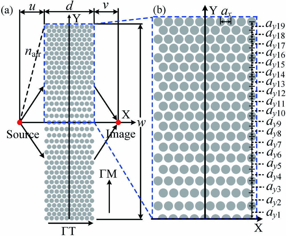
In this Letter, taking a two-dimensional triangular lattice PC without gradient as the basic model, the GPC with a gradient of lattice spacing is obtained by modifying the lattice spacing of the PC. The PC and GPC are composed of dielectric rods in the air background. The geometry of the GPC flat lens is shown in Fig. 1. The thickness , where is the lattice constant. The value of is 1 μm. The width ; the object distance . The image distance , assuming the coordinate of the image point is . The rod radius , and the material is . The refractive index of is approaching three[49] at the operating wavelength in this Letter. The GPC flat lens is symmetric about the X axis. Half of the GPC flat lens that is surrounded by the blue dashed line in Fig. 1(a) is enlarged and is shown in Fig. 1(b). The lattice spacing along the positive direction of the Y axis is altered, as shown in Fig. 1(b), while keeping the lattice spacing along the X direction constant, and . Without loss of generality, the change of is commonly linear, and the incremental step () is taken to be . In order to get better focusing effect, is set to the maximum value to increase the transmission of light. It should be noted that the value of is set as the lattice spacing of the triangular lattice PC for considering engineering preparation and light coupling capabilities[45–47].

Figure 1.(a) Model of the GPC flat lens. The lattice spacing (the subscript takes the value from 1 to 19) is decreased along the positive and negative directions of the Y axis; the lattice spacing is , and it stays the same along the X direction. (b) Half of the structure surrounded by the rectangular area with the blue dashed line in (a).
The TM polarization is only considered in our study. To precisely research the beam propagation characteristics of EFCs of the GPC, the band structure of the GPC, and the imaging characteristics of the GPC flat lens for point source, COMSOL Multiphysics based on the finite element method (FEM) is utilized for calculating the bands and EFCs and monitoring the electric fields of the flat lenses in this Letter.
Due to the aperiodicity of the lattice spacing distribution in our GPC, it is not possible to obtain the bands and EFCs directly using FEM[45]. It is necessary to, respectively, calculate the bands and EFCs of the Wigner–Seitz (WS) primitive cells modified by various lattice spacing and study the effect of various lattice spacing values on them. For the calculation of the bands and EFCs, the boundary condition of the WS primitive cell is set as a floquet-periodic boundary condition. The maximum mesh element size is less than , and the total number of mesh elements is 1616 in the WS primitive cell.
In order to calculate the band structure, a WS primitive cell from the complete unit cell is needed. The unit cell needs to be modified symmetrically by lattice spacing to get a complete unit cell, as shown in Fig. 2(a); from left to right, the unit cell of the triangular lattice PC is symmetrically modified, as shown by the black arrows. This modification not only leads to the decrease of symmetry of the unit cell, but also affects the WS primitive cell (surrounded by the red line) and the band structure.
Figure 2.(a) Unit cell of the triangular lattice PC and the unit cell modified by lattice spacing in real space. The WS primitive cells are surrounded by red lines. (b) The band structure of the WS primitive cell modified by lattice spacing . Inset is the first Brillouin zone, and the area around the letters is the irreducible Brillouin zone. The light cone is marked by the blue dotted line. (c) Analysis of the direction of beam propagation by EFCs. and , are negative and positive refractions, respectively[45].
Figure 2(b) shows the band structure of the WS primitive cell modified by lattice spacing . It can be found that the changes of the second and third bands around the point in both the and directions are very different, and a similar situation happens in both the and directions. This indicates that the EFCs of the two bands are not totally isotropic because of the decrease in symmetry caused by lattice modification.
According to the EFC theory, the beam propagation direction can be analyzed by using EFCs, as shown in Fig. 2(c). In the EFC theory, the relation between group velocity and wave vector is as follows[22]:
In Fig. 2(c), the left plot shows the light cone, and the right plot shows the EFC of the PC and two types of refractions. In the process of beam propagation, the vertical component of the wave vector is conserved, so the wave vectors in the PC can be or , and the corresponding group velocities are and , respectively. In the second band, the frequency of the EFCs gradually decreases along the radial outward direction, the actual group velocity is according to Eq. (1), and is in the opposite direction of the wave vector ; then, the negative refraction occurs and produces an NERI [50].
There is also an easy and quick way to determine if negative refraction has occurred. Unlike positive refraction, when negative refraction occurs, the incident and refracted () beams are on the same side of normal. The incident beam is in the same direction as the wave vector () in the air. So, the negative refraction is determined by and being on the same side of the normal.
Next, the EFCs modified by under various wavelengths are calculated and used to analyze whether the EFCs undergo negative refraction.
Taking the EFC of the second bands at a wavelength of 3.122 μm as an example to analyze the effect of various lattice spacing values on EFCs, the result is shown in Fig. 3. The shape and size of the EFC are sensitive to the modification of in Fig. 3, and the shape indeed is not isotropic. According to the EFC theory, EFCs affect the refraction angle, so different EFCs caused by different lattice spacings play key roles in achieving negative refraction imaging. In addition, also according to the EFC theory, it can be inferred that when is , the EFC is larger, and more beams of large angles can be coupled into the flat lens, which improves the imaging quality, compared with the values of , that is, .
Figure 3.EFCs of the second band affected by lattice spacings at the wavelength of 3.122 μm.
By calculation and analysis, the negative refraction can occur at wavelength in our GPC flat lens. Then, the imaging simulation of the point source using the GPC flat lens is carried out at those wavelengths. A large number of numerical calculations show that the GPC flat lens achieves three types of super-resolution imaging. The near-field super-resolution imaging is achieved at wavelength . The perfect imaging is achieved at wavelength . The far-field super-resolution imaging is achieved at wavelength . For each type of imaging, one wavelength is taken as an example to analyze negative refraction in detail. The wavelengths , , and are taken as examples.
For our GPC, various participates in the imaging process at the same time, and corresponds to incident angle of the beam; the smaller is, the smaller the incident angle is. Hence, the imaging analysis of GPC flat lens is very complicated. However, some incident beams with small angles near the center of the flat lens are taken as examples to analyze the negative refraction. Beams with small incident angles are the main component of imaging due to their short transmission distance and low evanescent wave attenuation. To avoid the similarity of EFCs modified by adjacent , the EFCs of the WS primitive cells modified by lattice spacing and are taken as examples to analyze the negative refraction. As shown in Figs. 4(a)–4(c), the EFCs of the WS primitive cells modified by lattice spacing and are illustrated, respectively, by red curves and blue curves.
Figure 4.EFCs of the second bands of WS primitive cells modified by lattice spacing (red curves, corresponding to ) and (blue curves, corresponding to ) at specific wavelengths: (a) , (b) , and (c) . The black dashed circles are the light cones. The black arrows represent wave vectors () in the air, and the red and blue arrows represent group velocities (). (d) The variation of NERI with at the wavelengths of , , and .
The normalized frequency is defined as , so , , and . From the three frequencies marked by different colors in Fig. 2(b), three frequencies can be found across both the second and third bands, so there are two EFCs. However, the frequency of EFCs in the third band increases gradually along the radial direction and can only produce positive refraction, so only EFCs of the second band are plotted in Figs. 4(a)–4(c). As shown in Fig. 4(c), at wavelength and in the EFC of the WS primitive cell modified by lattice spacing , when the beam is incoming at the corresponding incident angle of , the wave vector in the air (black arrow) and the refracted beam (red arrow) in the second band are on the same side of the normal line. In other case, the same is true. Therefore, the negative refractions are achieved in the second band.
Then, we calculated the variation of the NERI of half of the GPC with the lattice spacing , as shown in Fig. 4(d). It can be found that the GPC corresponds to a kind of gradient NERI structure, respectively, at , , and .
This is in good agreement with Ref. [29]. It should be noted that the NERI corresponds to the incident angle because of the non-isotropic EFCs, and the NERI only works when light travels in the direction of . From Fig. 4(d), the three gradient NERI structures are not identical in gradient refractive index, which makes it possible to control the wide range of image distance variation using point sources in a small range of wavelength.
The imaging behavior of the flat lens is researched next. For the integrity of the research, the imaging characteristics of the GPC and that of the PC are compared. Each layer of the PC being compared has the same lattice spacing, i.e., , and other parameters except related to lattice spacing are the same as that of the GPC. In the simulation of imaging, the GPC or PC flat lens is placed in a rectangular frame whose boundary condition is set as the scattering boundary condition. The two-dimensional targeted region is computed with an auto triangular mesh subdivision method. The maximum mesh element size is less than , and the total number of mesh elements is more than in the targeted region. Then, setting the incident wavelength of the point source as , , and to traverse the PC and GPC flat lenses, respectively, the electric fields of the GPC and PC flat lenses are monitored. The positions of the image points and the full width at half-maximum (FWHM) values of the beam at the image points of the flat lenses are recorded.
The imaging fields of the PC and GPC flat lenses are shown in Figs. 5(a)–5(c) and 5(d)–5(f), respectively. In all imaging fields, the image points are marked by white arrows. The intensities of the axial plane of the image point are shown in Figs. 6(a)–6(c), respectively. The intensities of the image plane of image point are shown in Figs. 6(d)–6(f), respectively.
Figure 5.Imaging fields of the PC and GPC flat lenses for the point source at specific wavelengths. PC: (a) , (b) , (c) ; GPC: (d) , (e) , (f) .
Figure 6.Magnitudes of the axial plane of imaging fields: (a) , (b) , (c) . Magnitudes of the image plane of imaging fields: (d) , (e) , (f) .
In the imaging system, the diffraction limit is [51], so if , the flat lenses break through the diffraction limit to achieve super-resolution imaging.
From Figs. 6(a) and 6(d), it can be seen that the image distance (i.e., ), , the image distance (i.e., ), and . That is to say, the GPC flat lens achieves near-field super-resolution imaging at wavelength , while the resolution of the PC flat lens is close to the diffraction limit but does not exceed it under a fitting accuracy of 0.1 nm. From Figs. 6(b) and 6(e), the image distance (i.e., ), , the image distance (i.e., ), and ; that is, the super-resolution imaging is achieved by the GPC flat lens at wavelength . Moreover, , so the imaging achieved by the GPC flat lens is approaching perfect imaging. In Figs. 6(c) and 6(f), it can be known that the image distance (i.e., ), , the image distance (i.e., ), and . The GPC flat lens achieves far-field super-resolution imaging at wavelength . Therefore, three types of super-resolution imaging are achieved by the GPC flat lens.
Next, the GPC flat lens was analyzed using two point sources with the wavelength of 3.231 μm, and the result is shown in Fig. 7. As can be seen from Fig. 7, the GPC flat lens achieves off-axis point source imaging. It is known to all that the imaging achieved by traditional lens is inverted, while the GPC flat lens uses negative refraction imaging, so the imaging achieved by it is not inverted; that is, imaging 1 and imaging 2 are the imaging of sources 1 and 2, respectively. It is worth noting that, since the GPC flat lens follows the imaging rule of under perfect imaging, the relative distance between the two image points should be close to that between the two source points[52]. This result strongly proves the perfect imaging characteristics of the GPC flat lens.
Figure 7.Off-axis point source imaging of the GPC flat lens at a wavelength of 3.231 μm.
Next, the relationship between FWHM and the flat lens thickness (represented by the number of scatterers on the X axis) was investigated to optimize the flat lens.
The results are shown in Table 1. The slashes indicate that the PC flat lens cannot achieve the imaging. From Table 1, it can be seen that the imaging performance of the GPC flat lens is generally better than that of the PC flat lens.
| Number of Scatterers on the X Axis | FWHM of PC Flat Lens | FWHM of GPC Flat Lens |
|---|
| λ1 | λ2 | λ3 | λ1 | λ2 | λ3 |
|---|
| 5 | / | 0.38 | / | 0.44 | 0.56 | 0.64 |
| 7 | 0.52 | 0.41 | / | 0.40 | 0.49 | 0.66 |
| 9 | 0.52 | 0.56 | 0.62 | 0.42 | 0.44 | 0.48 |
| 11 | / | 0.37 | / | 0.46 | 0.47 | 0.50 |
| 13 | / | / | / | 0.48 | 0.61 | 0.61 |
Table 1. The FWHM of Image Points Under the Different Thicknesses of GPC and PC Flat Lenses at Wavelengths , , and
For the GPC flat lens, the overall imaging effect is the best when the number of scatterers on the X axis is set to nine (i.e., the GPC structure in this Letter). In addition, the GPC flat lens can adjust the interval between different types of imaging wavelengths by increasing the lattice constant , so as to meet the requirements of practical application and reduce the difficulty of structure preparation.
Finally, the fabrication method and the plane wave focus of the GPC lens are discussed extensively. Firstly, the GPC is small in size, so the preparation technology can be considered as a focused ion beam[53], electron beam lithography[54], and nanoimprint lithography[55]. Secondly, in order to make the GPC lens focus the plane wave, the flat lens can be converted into a plano-concave lens with lattice spacing of to simply, as shown in Fig. 8(a). Then, a plane wave of wavelength is set to traverse the plano-concave lens, and the focus field is shown in Fig. 8(b). It can be clearly seen that the plane wave is focused after traversing the plano-concave lens. The FWHM of the image point is , breaking through the diffraction limit.
Figure 8.(a) GPC plano-concave lens model. (b) Focus field of the GPC plano-concave lens for the plane wave.
In conclusion, we performed the lattice spacing modulation of the triangular lattice PC in order to obtain a GPC with a gradient of lattice spacing. The negative refraction imaging behavior of the designed device was analyzed theoretically and indicated that the modification of lattice spacing is sufficient to achieve multiple types of high-quality imaging for the point source in the second band, that is, the near-field super-resolution, perfect imaging, and far-field super-resolution. In addition, the GPC lens also focuses the plane wave by changing the flat shape of lens to a plano-concave shape simply. The lens may replace conventional PC and GPC lenses and become one of the important devices in medicine, biology, and optics imaging fields.
References
[1] H. Huan, H. Jile, Y. Tang, X. Li, Z. Yi, X. Gao, X. Chen, J. Chen, P. Wu. Micromachines, 11, 309(2020).
[2] H. Wu, H. Jile, Z. Chen, D. Xu, Z. Yi, X. Chen, J. Chen, W. Yao, P. Wu, Y. Yi. Micromachines, 11, 189(2020).
[3] J. Li, X. Chen, Z. Yi, H. Yang, Y. Tang, Y. Yi, W. Yao, J. Wang, Y. Yi. Mater. Today. Energy, 16, 100390(2020).
[4] J. Li, Z. Chen, H. Yang, Z. Yi, X. Chen, W. Yao, T. Duan, P. Wu, G. Li, Y. Yi. Nanomaterials, 10, 257(2020).
[5] F. Qin, Z. Chen, X. Chen, Z. Yi, W. Yao, T. Duan, P. Wu, H. Yang, G. Li, Y. Yi. Nanomaterials, 10, 207(2020).
[6] S. John. Phys. Rev. Lett., 58, 2486(1987).
[7] Y. S. Chan, C. T. Chan, Z. Y. Liu. Phys. Rev. Lett., 80, 956(1998).
[8] E. Liu, W. Tan, B. Yan, J. Xie, R. Ge, J. Liu. J. Opt. Soc. Am. A, 35, 431(2018).
[9] Q. Liu, B. Yan, J. Liu. Appl. Phys. Express, 12, 052014(2019).
[10] E. Liu, S. Liang, J. Liu. Superlattice. Microst., 130, 61(2019).
[11] E. Liu, W. Tan, B. Yan, J. Xie, R. Ge, J. Liu. J. Phys. D: Appl. Phys., 52, 325110(2019).
[12] Z. Huo, E. Liu, J. Liu. Chin. Opt. Lett., 18, 030603(2020).
[13] Y.-F. Zhao, Z.-M. Wang, Z.-J. Jiang, C.-X. Yue, X. Chen, J.-Z. Wang, J.-J. Liu. J. Infrared. Millim. W., 36, 342(2017).
[14] A. A. Rifat, F. Haider, R. Ahmed, G. A. Mahdiraji, F. R. M. Adikan, A. E. Miroshnichenko. Opt. Lett., 43, 891(2018).
[15] R. Ge, J. Xie, B. Yan, E. Liu, W. Tan, J. Liu. J. Opt. Soc. Am. A, 35, 992(2018).
[16] A. Shi, R. Ge, J. Liu. Superlattice. Microst., 133, 106198(2019).
[17] I. Abood, S. Elshahat, K. Khan, L. Bibbò, A. Yadav, Z. Ouyang. Opt. Commun., 439, 181(2019).
[18] B. Yan, J. Xie, E. Liu, Y. Peng, R. Ge, J. Liu, S. Wen. Phys. Rev. Appl., 12, 044004(2019).
[19] T. Hou, R. Ge, W. Tan, J. Liu. J. Phys. D: Appl. Phys., 53, 075104(2020).
[20] R. Ge, B. Yan, J. Xie, E. Liu, W. Tan, J. Liu. J. Magn. Magn. Mater., 500, 166367(2020).
[21] Z. Guo, B. Yan, J. Liu. J. Opt., 22, 035002(2020).
[22] M. Notomi. Phys. Rev. B, 62, 10696(2000).
[23] S. Xiao, M. Qiu, Z. Ruan, S. He. Appl. Phy. Lett., 85, 4269(2004).
[24] Y. Fang. Laser Phys. Lett., 2, 502(2005).
[25] R. Moussa, S. Foteinopoulou, L. Zhang, G. Tuttle, K. Guven, E. Ozbay, C. M. Soukoulis. Phys. Rev. B, 71, 085106(2005).
[26] E. Centeno, D. Cassagne. Opt. Lett., 30, 2278(2005).
[27] T. Decoopman, G. Tayeb, S. Enoch, D. Maystre, B. Gralak. Phys. Rev. Lett., 97, 073905(2006).
[28] X. Zhang, Z. Liu. Nat. Mater., 7, 435(2008).
[29] H. Kurt, E. Colak, O. Cakmak, H. Caglayan, E. Ozbay. Appl. Phy. Lett., 93, 171108(2008).
[30] Y. Fang, Z. Ouyang. Chin. Opt. Lett., 6, 157(2008).
[31] H. Wu, L. Y. Jiang, W. Jia, X. Y. Li. J. Opt., 13, 095103(2011).
[32] P. Shi, K. Huang, Y.-P. Li. J. Opt. Soc. Am. A, 28, 2171(2011).
[33] L. Jiang, H. Wu, X. Li. Opt. Lett., 37, 1829(2012).
[34] Q. Zhang, X. Li, M. Gu. J. Opt., 15, 075102(2013).
[35] Z. Huang, E. E. Narimanov. J. Opt., 16, 114009(2014).
[36] W. Liu, X. Sun, M. Gao, S. Wang. Opt. Commun., 364, 225(2016).
[37] Y.-Y. Zhao, Y.-L. Zhang, M.-L. Zheng, X.-Z. Dong, X.-M. Duan, Z.-S. Zhao. J. Opt., 19, 015605(2017).
[38] M. Turduev, E. Bor, H. Kurt. J. Phys. D: Appl. Phys., 50, 275105(2017).
[39] M. Alipour-Beyraghi, T. F. Khalkhali, A. Bananej, J. Mostafavi-Amjad. Opt. Commun., 420, 133(2018).
[40] F. Xia, S. Li, K. Zhang, L. Jiao, W. Kong, L. Dong, M. Yun. Phys. B, 545, 233(2018).
[41] T. Zhou, W. Tan, B. Yan, E. Liu, J. Liu. Superlattice. Microst., 124, 176(2018).
[42] C. Zhang, Z. Jiang, W. Tan, R. Ge, J. Liu. J. Opt. Soc. Am. A, 35, 1701(2018).
[43] W. Zhang, W. Tan, Q. Yang, T. Zhou, J. Liu. J. Opt. Soc. Am. B, 35, 2364(2018).
[44] W. Tan, E. Liu, B. Yan, J. Xie, R. Ge, D. Tang, J. Liu, S. Wen. Appl. Phys. Express, 11, 092002(2018).
[45] J. Xie, J. Wang, R. Ge, B. Yan, E. Liu, W. Tan, J. Liu. J. Phys. D: Appl. Phys., 51, 205103(2018).
[46] S. Liang, J. Xie, P. Tang, J. Liu. Opt. Express, 27, 9601(2019).
[47] Y. Cen, J. Xie, J. Liu. Chin. Opt. Lett., 17, 080501(2019).
[48] J. B. Pendry. Phys. Rev. Lett., 85, 3966(2000).
[49] S. Adachi. J. Appl. Phys., 58, R1(1985).
[50] L. Feng, X.-P. Liu, M.-H. Lu, Y.-B. Chen, Y.-F. Chen, Y.-W. Mao, J. Zi, Y.-Y. Zhu, S.-N. Zhu, N.-B. Ming. Phys. Rev. Lett., 96, 014301(2006).
[51] E. Abbe. Archiv f. mikrosk. Anatomie., 9, 413(1873).
[52] F. Monticone, C. A. Valagiannopoulos, A. Alu. Phys. Rev. X, 6, 041018(2016).
[53] C. Enkrich, R. Perez-Willard, D. Gerthsen, J. Zhou, T. Koschny, C. M. Soukoulis, M. Wegener, S. Linden. Adv. Mater., 17, 2547(2005).
[54] G. Dolling, C. Enkrich, M. Wegener, C. M. Soukoulis, S. Linden. Science, 312, 892(2006).
[55] L. J. Guo. Adv. Mater., 19, 495(2007).