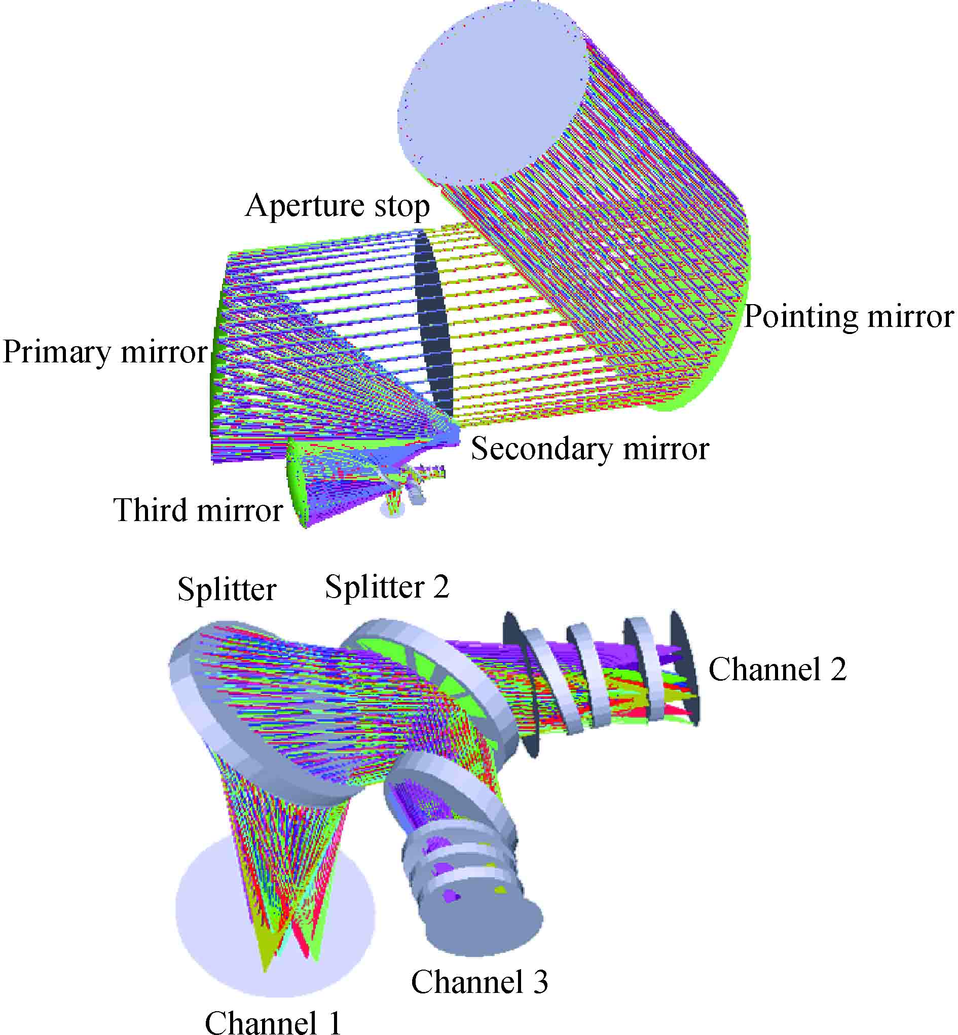
Fig. 1. Schematic diagram of light path
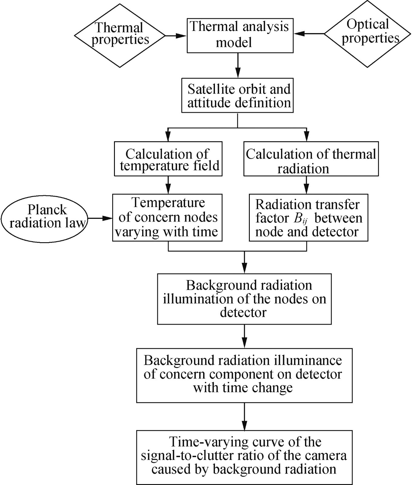
Fig. 2. Calculating process of instrument background radiation stray light for TRSLIM
Fig. 3. Thermal network model
Fig. 4. External heat flow into the hood
Fig. 5. Temperature curve of primary mirror in one day
Fig. 6. Temperature gradient curve of primary mirror in one day
Fig. 7. Radiation curve of instrument background radiation produced by primary mirror on detector in one day
Fig. 8. Total instrument background radiation curve generated by optical-mechanical components on detector in one day
Fig. 9. SCR curve formed by instrument background radiation in one day
Fig. 10. Variation curve of SCR at band 3 in one day
| Time | Temperature/°C | Emissivity | Miλ/(
W/m2)
| | 12:00 | −1.3 | 0.04 | 0.049 0 | | 20:00 | −5.6 | 0.04 | 0.040 5 | | 6:00 | 2.3 | 0.04 | 0.057 2 |
|
Table 1. Radiation calculation of primary mirror at different time in infrared band
| Cond_id | Node 1 | Node 2 | Area*e*Bij | Bij | Bji | | 1 | COMET.9284 | COMET.6790 | 2.728 026e-05 | 0.018 532 | 0.012 89 | | 2 | COMET.9284 | COMET.6791 | 5.640 484e-07 | 0.003 455 921 | 0.002 322 2 | | 3 | COMET.9284 | COMET.7308 | 1.156 538e-06 | 0.013 559 96 | 0.001 076 | | 4 | COMET.9284 | COMET.7309 | 1.401 487e-06 | 0.007 363 961 | 0.003 127 9 | | …… | | | | | | | N-3
| COMET.9310 | COMET.7309 | 6.087 829E-08 | 5.18E-05 | 0.001 187 | | N-2
| COMET.9310 | COMET.7310 | 1.103 783E-06 | 0.009 397 84 | 0.004 149 | | N-1
| COMET.9310 | COMET.7311 | 6.306 837E-07 | 0.005 369 77 | 0.001 819 | | N | COMET.9310 | COMET.7312 | 2.469 422E-06 | 0.002 102 518 | 0.007 124 |
|
Table 2. Energy transfer factor Bijof nodes of primary mirror to detector
| Cond_id | Node 1 | Node 2 | Bij | Ej/
(W/m2)
| E/(W/m2)
| | 1 | COMET.9284 | COMET.6779 | 0.005 853 2 | 0.000 726 | 3.712E-04 | | 2 | COMET.9284 | COMET.6780 | 0.000 345 592 1 | 0.000 135 | | 3 | COMET.9284 | COMET.7270 | 0.003 559 96 | 0.000 532 | | 4 | COMET.9284 | COMET.7271 | 0.001 363 961 | 0.000 289 | | …… | | | | | | N-3
| COMET.9310 | COMET.7271 | 5.18E-05 | 2.03E-06 | | N-2
| COMET.9310 | COMET.7272 | 0.009 397 84 | 0.000 368 | | N-1
| COMET.9310 | COMET.7273 | 0.000 536 977 | 0.000 21 | | N | COMET.9310 | COMET.7274 | 0.002 102 518 | 8.24E-05 |
|
Table 3. Radiation calculation of nodes of primary mirror on detector at 12:00
| Cond_id | Node 1 | Node 2 | Bij | Ej/(W/m2)
| E/(W/m2)
| | 1 | COMET.9284 | COMET.6779 | 0.005 853 2 | 0.000 595 | 1.820E-04 | | 2 | COMET.9284 | COMET.6780 | 0.000 345 592 1 | 0.000 111 | | 3 | COMET.9284 | COMET.7270 | 0.003 559 96 | 0.000 435 | | 4 | COMET.9284 | COMET.7271 | 0.001 363 961 | 0.000 236 | | …… | | | | | | N-3
| COMET.9310 | COMET.7271 | 5.18E-05 | 1.66E-06 | | N-2
| COMET.9310 | COMET.7272 | 0.009 397 84 | 0.000 302 | | N-1
| COMET.9310 | COMET.7273 | 0.000 536 977 | 0.000 172 | | N | COMET.9310 | COMET.7274 | 0.002 102 518 | 6.75E-05 |
|
Table 4. Radiation calculation of nodes of primary mirror on detector at 20:00
| Cond_id | Node 1 | Node 2 | Bij | Ej//(W/m2)
| E/(W/m2)
| | 1 | COMET.9284 | COMET.6779 | 0.005 853 2 | 0.000 854 | 5.855E-04 | | 2 | COMET.9284 | COMET.6780 | 0.000 345 592 1 | 0.000 159 | | 3 | COMET.9284 | COMET.7270 | 0.003 559 96 | 0.000 625 | | 4 | COMET.9284 | COMET.7271 | 0.001 363 961 | 0.000 339 | | …… | | | | | | N-3
| COMET.9310 | COMET.7271 | 5.18E-05 | 2.39E-06 | | N-2
| COMET.9310 | COMET.7272 | 0.009 397 84 | 0.000 433 | | N-1
| COMET.7273 | 0.000 536 977 | 0.000 248 | | N | COMET.9310 | COMET.7274 | 0.002 102 518 | 9.69E-05 |
|
Table 5. Radiation calculation of nodes of primary mirror on detector at 6:00
| Time | On-orbit test values | TRSLIM | TSLAM | | Simulation value | Errors from on-orbit test values | Simulation value | Errors from on-orbit test values | | 3:00 | 0.059 | 0.06 | 1.69% | 0.112 | 89.83% | | 8:00 | 0.064 | 0.074 | 15.63% | 0.13 | 103.13% | | 12:00 | 0.078 | 0.091 | 16.67% | 0.144 | 84.62% | | 15:00 | 0.089 | 0.103 | 15.73% | 0.189 | 112.36% | | 18:00 | 0.095 | 0.109 | 14.74% | 0.204 | 114.74% | | 22:00 | 0.089 | 0.098 | 10.11% | 0.179 | 101.12% |
|
Table 6. Comparison of SCR from on-orbit measured, TRSLIM and TSLAM