
Lu Qiang. Thermal radiation stray light integration method of infrared camera in geostationary orbit[J]. Infrared and Laser Engineering, 2020, 49(5): 20190457
- Infrared and Laser Engineering
- Vol. 49, Issue 5, 20190457 (2020)
Abstract
Keywords
0 Introduction
For the three-axis stabilized satellite in geosynchronous orbit, its space environment temperature is complex. The satellite temperature is affected by the sun, which not only changes with the season, but also varies greatly at different time of the same day. The temperature inside the camera determines the background radiation of the instrument and affects the dynamic range of the camera. Therefore, the simulation and calculation of the background radiation of the instrument becomes an important factor affecting the accuracy and quantification of the infrared camera in geosynchronous orbit.
For the analysis of stray light in instrument background, the traditional stray light analysis method (TSLAM) is based on Tracepro, Lighttools and other software, which greatly simplifies the temperature field of each component. Usually, the radiation analysis of uniform temperature field can not simulate the actual non-uniform temperature field in orbit, nor can the real-time calculation of the temperature field changing in one day being carried out[
It can be seen that the temperature field of geosynchronous orbit varies greatly with time. The background radiation of the instrument caused by the temperature field has become an important factor affecting the imaging quality of infrared cameras. Real-time analysis of the influence of stray light from instrument background radiation on camera detection ability caused by non-uniform temperature field in one day is a necessary step in optical system design. In this paper, the thermal radiation stray light integration method (TRSLIM) is proposed to analyze the instrument background radiation of on-orbit infrared camera. The temperature field of each optical component is directly simulated by thermal radiation stray light software. The temperature field is real-time and has temperature gradient, which tends to be more realistic. The background radiation of the instrument on the detector can be calculated by combining the temperature field of each node of the opto-mechanical element with the radiation transfer factor. The signal-to-clutter ratio (SCR) of the camera can be calculated by combining the radiation characteristics of the target.
1 Optical structure of camera and illumination analysis of target
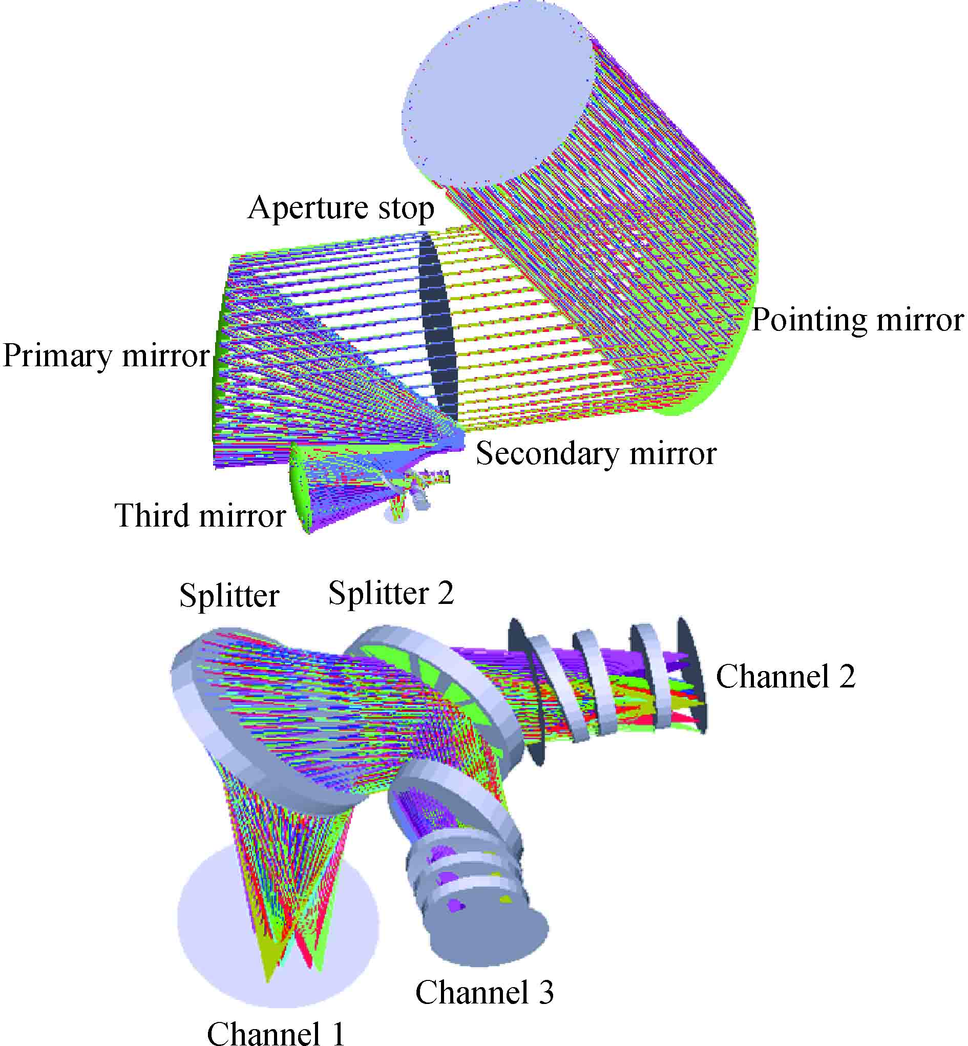
The optical model of the space camera is an off-axis three-mirror structure. The optical path diagram is shown in
![]()
Figure 1.Schematic diagram of light path
For channel 3 (infrared channel), the radiation flux of the point target received by the camera on the focal plane device is as follows:
The irradiance of the point target received on the focal plane is as follows:
Among them, J is the radiation intensity of the point target; I is the detection distance of the point target; τa is the atmospheric transmittance in infrared band, the value is 0.65; τ0 is the optical transmittance in the channel 3 of the camera, the value is 0.48; Enc is the concentration of diffraction energy in one pixel of the channel 3 of the camera, the value is 70%;D0 is the optical aperture of the optical system, and a is the pixel size. Finally, the irradiance of the point target on the detector of channel 3 is calculated to be 1.887×10⁻³ W/m2.
2 Thermal radiation stray light integration method (TRSLIM)
2.1 Radiation transfer factor
In recent years, the commercial software Structural/Thermal/Optics Performance (STOP) for optical-mechanical thermal integration analysis has been gradually integrated into the engineering application[
At present, TracePro and Lighttools are mainly used to analyze instrument background radiation. These software uses mature Monte-Carlo Method (MCM) for ray tracing. However, the stray light software itself can not analyze the orbital parameters of the space camera and the periodic variation of the temperature field of the instrument, so the non-real-time and uniform temperature field is often used for approximate analysis. Thermal analysis software such as Thermal Desktop, TMG and so on, also uses MCM calculation method, but can obtain real-time instrument temperature field with temperature gradient. The radiation transfer factor is introduced into the thermal software, which includes the energy exchange between the opto-mechanical elements and the focal plane, which is concerned by stray light analysis. The radiation transfer factor remains unchanged in the process of solving the energy transfer problem. Finally, the instrument background radiation can be calculated by the instrument temperature field and the radiation transfer factor.
Therefore, it is feasible to use thermal analysis software for stray light analysis.
The radiation transfer factor Bij is defined as the percentage of the energy directly projected from surface 1 to surface 2 to the radiation energy of surface 1. The definition can be written as:[
Among them, Q1 is the effective radiation of surface 1 and Q12 is the projection radiation of surface 1 to surface 2.
If the number of volume Vi and panel Sj in the thermal radiation system is Nand M, the energy equation of volume Vi is
The energy equation of panel Si is
The radiation transfer factor emitted by volume Vi and absorbed by panel Sj is as follows:
Among them, Ni(Vi) is the total number of energy beams emitted by volume Vi and Nj(Sj) is the total number of energy beams absorbed by panel Sj.
2.2 Calculation Principle of TRSLIM
The method of calculating instrument background radiation for thermal radiation stray light integrated analysis is based on the orbital model and the radiation characteristics of the camera itself. The thermal analysis of the camera is carried out, and the non-uniform temperature field of each optical component of the camera is obtained. For the element of interest, the node temperature and the specific emissivity of the element with time are taken and calculated according to Planck's law of radiation. The radiation illumination of the element node with time varying in the spectrum of interest is as follows:
Through the thermal radiation module of the thermal radiation stray light integrated analysis software, the radiation transfer factor Bij between each element node and detector node is calculated, and then the instrument background irradiance of each element on the detector which changes with time is calculated. The calculation formula is as follows:
Then, the total instrument background irradiance on the detector is obtained by adding the instrument background irradiance of each component. According to the calculation results of the irradiance of the point target on the detector in the last section, the SCR caused by the instrument background radiation with time is calculated. The calculation process is shown in
![]()
Figure 2.Calculating process of instrument background radiation stray light for TRSLIM
2.3 Modeling and input conditions
2.3.1 Establishment of model
Because of the complex thermal characteristics of space camera in orbit, it is necessary to simplify the geometric model, the external heat flow and the thermal characteristics of nodes before building the model. The simplification is mainly based on the technical status and heat transfer characteristics of the space camera. In the process of building thermal model, the partition of nodes and grids is also an important step. If the main thermal characteristics of space camera can be embodied, the number of nodes will be reduced as much as possible. If the optical-mechanical element is isothermal, it can be regarded as a node. If the temperature gradient of the optical-mechanical element is large, the node should be subdivided. In addition, the space camera is divided into several different components, including the main frame component, the pointing mechanism component, the main optical component, the rear light path component and the refrigerator Dewar component. The thermal contact relationship between the components is defined separately and connected through the grid assembly relationship. The final thermal analysis model of space camera is as shown in
![]()
Figure 3.Thermal network model
2.3.2 Selection of calculating conditions
The orbit of the space camera is geosynchronous.
![]()
Figure 4.External heat flow into the hood
2.4 Calculation results
The TRSLIM is carried out for the infrared channel of channel 3. Firstly, the background irradiance of each optical-mechanical element should be calculated.
The temperature change curve and temperature gradient change curve of each optical-mechanical element in one day were obtained by thermal model and orbit parameters. Take the primary mirror as an example,
| Time | Temperature/°C | Emissivity | |
| 12:00 | −1.3 | 0.04 | 0.049 0 |
| 20:00 | −5.6 | 0.04 | 0.040 5 |
| 6:00 | 2.3 | 0.04 | 0.057 2 |
Table 1. Radiation calculation of primary mirror at different time in infrared band
| Cond_id | Node 1 | Node 2 | Area*e* | ||
| 1 | COMET.9284 | COMET.6790 | 2.728 026e-05 | 0.018 532 | 0.012 89 |
| 2 | COMET.9284 | COMET.6791 | 5.640 484e-07 | 0.003 455 921 | 0.002 322 2 |
| 3 | COMET.9284 | COMET.7308 | 1.156 538e-06 | 0.013 559 96 | 0.001 076 |
| 4 | COMET.9284 | COMET.7309 | 1.401 487e-06 | 0.007 363 961 | 0.003 127 9 |
| …… | |||||
| COMET.9310 | COMET.7309 | 6.087 829E-08 | 5.18E-05 | 0.001 187 | |
| COMET.9310 | COMET.7310 | 1.103 783E-06 | 0.009 397 84 | 0.004 149 | |
| COMET.9310 | COMET.7311 | 6.306 837E-07 | 0.005 369 77 | 0.001 819 | |
| COMET.9310 | COMET.7312 | 2.469 422E-06 | 0.002 102 518 | 0.007 124 |
Table 2. Energy transfer factor Bijof nodes of primary mirror to detector
| Cond_id | Node 1 | Node 2 | |||
| 1 | COMET.9284 | COMET.6779 | 0.005 853 2 | 0.000 726 | 3.712E-04 |
| 2 | COMET.9284 | COMET.6780 | 0.000 345 592 1 | 0.000 135 | |
| 3 | COMET.9284 | COMET.7270 | 0.003 559 96 | 0.000 532 | |
| 4 | COMET.9284 | COMET.7271 | 0.001 363 961 | 0.000 289 | |
| …… | |||||
| COMET.9310 | COMET.7271 | 5.18E-05 | 2.03E-06 | ||
| COMET.9310 | COMET.7272 | 0.009 397 84 | 0.000 368 | ||
| COMET.9310 | COMET.7273 | 0.000 536 977 | 0.000 21 | ||
| COMET.9310 | COMET.7274 | 0.002 102 518 | 8.24E-05 |
Table 3. Radiation calculation of nodes of primary mirror on detector at 12:00
| Cond_id | Node 1 | Node 2 | |||
| 1 | COMET.9284 | COMET.6779 | 0.005 853 2 | 0.000 595 | 1.820E-04 |
| 2 | COMET.9284 | COMET.6780 | 0.000 345 592 1 | 0.000 111 | |
| 3 | COMET.9284 | COMET.7270 | 0.003 559 96 | 0.000 435 | |
| 4 | COMET.9284 | COMET.7271 | 0.001 363 961 | 0.000 236 | |
| …… | |||||
| COMET.9310 | COMET.7271 | 5.18E-05 | 1.66E-06 | ||
| COMET.9310 | COMET.7272 | 0.009 397 84 | 0.000 302 | ||
| COMET.9310 | COMET.7273 | 0.000 536 977 | 0.000 172 | ||
| COMET.9310 | COMET.7274 | 0.002 102 518 | 6.75E-05 |
Table 4. Radiation calculation of nodes of primary mirror on detector at 20:00
![]()
Figure 5.Temperature curve of primary mirror in one day
![]()
Figure 6.Temperature gradient curve of primary mirror in one day
| Cond_id | Node 1 | Node 2 | |||
| 1 | COMET.9284 | COMET.6779 | 0.005 853 2 | 0.000 854 | 5.855E-04 |
| 2 | COMET.9284 | COMET.6780 | 0.000 345 592 1 | 0.000 159 | |
| 3 | COMET.9284 | COMET.7270 | 0.003 559 96 | 0.000 625 | |
| 4 | COMET.9284 | COMET.7271 | 0.001 363 961 | 0.000 339 | |
| …… | |||||
| COMET.9310 | COMET.7271 | 5.18E-05 | 2.39E-06 | ||
| COMET.9310 | COMET.7272 | 0.009 397 84 | 0.000 433 | ||
| COMET.7273 | 0.000 536 977 | 0.000 248 | |||
| COMET.9310 | COMET.7274 | 0.002 102 518 | 9.69E-05 |
Table 5. Radiation calculation of nodes of primary mirror on detector at 6:00
![]()
Figure 7.Radiation curve of instrument background radiation produced by primary mirror on detector in one day
![]()
Figure 8.Total instrument background radiation curve generated by optical-mechanical components on detector in one day
![]()
Figure 9.SCR curve formed by instrument background radiation in one day
3 On-orbit background radiation measurement
When the satellite attitude is stable to the ground, the SCR varies with the temperature field of the instrument as shown in
![]()
Figure 10.Variation curve of SCR at band 3 in one day
The instrument background radiation of Channel 3 is simulated by TRSLIM and TSLAM respectively.
In TSLAM, the temperature field is several characteristic temperature conditions provided by the thermal control personnel, and then these temperature fields are manually assigned to the optical and mechanical components in TracePro for background radiation simulation. It is impossible to calculate the changing temperature field in real time, and the simulation time takes one or two weeks. If TRSLIM is used, the temperature field of each optical machine element is the real-time temperature field on-orbit simulated directly by the thermal radiation stray light integrated software. Combined with the radiation factor, the instrument background radiation can be calculated directly. The simulation time is only half a day, which greatly improves the efficiency.
It can be seen that TRSLIM has two advantages over TSLAM. First, the real-time calculation of the SCR can be obtained by the temperature field changing with time. The background radiation analysis and thermal analysis is integrated into one process. Secondly, the non-uniform temperature field in orbit can be simulated. The temperature field is closer to the actual situation in orbit, and the simulation accuracy is improved greatly.
| Time | On-orbit test values | TRSLIM | TSLAM | ||
| Simulation value | Errors from on-orbit test values | Simulation value | Errors from on-orbit test values | ||
| 3:00 | 0.059 | 0.06 | 1.69% | 0.112 | 89.83% |
| 8:00 | 0.064 | 0.074 | 15.63% | 0.13 | 103.13% |
| 12:00 | 0.078 | 0.091 | 16.67% | 0.144 | 84.62% |
| 15:00 | 0.089 | 0.103 | 15.73% | 0.189 | 112.36% |
| 18:00 | 0.095 | 0.109 | 14.74% | 0.204 | 114.74% |
| 22:00 | 0.089 | 0.098 | 10.11% | 0.179 | 101.12% |
Table 6. Comparison of SCR from on-orbit measured, TRSLIM and TSLAM
4 Summary
In this paper, the TRSLIM is used to analyze the instrument background radiation of on-orbit infrared camera. The approximate temperature and uniform temperature field in the TSLAM are replaced by the real temperature field which tends to be on-orbit and has a temperature gradient. Combined with the radiation transfer factor, the background radiation of the instrument and the SCR of the camera on the detector is calculated. Comparing the SCR calculated by TRSLIM and TSLAM, the error of TRSLIM is less than 17%. Compared with the TSLAM, the TRSLIM is real-time and intuitive, the calculation results are closer to the actual situation in orbit, and has higher simulation efficiency and accuracy.
References
[1] Fei Zhao, Sen Wang. Study of stray light for the Xinglong 1-meter optical telescope. Astronomical Research & Technology, 7, 158-167(2010).
[2] Qiang Huang, Xinhua Niu, Xuemin Shen. Stray radiation analysis caused by interior heat radiation in infrared optical systems. Infrared Technology, 28, 348-352(2006).
[5] Weili Wang, Yong Lyu, Xiaoying Li. Stray light analysis on infrared channel of dual-band imaging system. Journal of Applied Optics, 39, 262-267(2018).
[8] Jiaqiang Yang, Ronggang Li, Qingqing Peng. Research of stray light in the IR system based on Lighttools and Matlab. Laser & Infrared, 44, 888-891(2014).
[9] Zurmehly G. Thermal structural analysis of the GOES scan mirr’s onbit perfmance[C]SPIE, 1991, 1532: 170176.
[10] Lightsey Paul A, Wei Zongying. Stray light perfmance f the James Webb Space Telescope[C]SPIE, 2014, 9143: 91433P.
[11] Gerhard S, David C, Gerard P. Advancements in Integrated StructuralThermalOptical (STOP) analysis of optical systems[C]SPIE, 2007, 6675: 66750D.
[12] Stoeckel Gerhard P, Doyle Keith B. Integrated optomechanical analysis testing software development at MIT Lincoln Labaty[C] SPIE, 2013,8840:88400E.
[13] Min Guirong. Satellite Thermal Control Technology [M]. Beijing: Aerospace Press, 1991.

Set citation alerts for the article
Please enter your email address
© Copyright 2018-2021 | Chinese Laser Press. All Rights Reserved 沪ICP备15018463号-20