
Esrom Kifle, Pavel Loiko, Javier Rodríguez Vázquez de Aldana, Carolina Romero, Airán Ródenas, Sun Yung Choi, Ji Eun Bae, Fabian Rotermund, Viktor Zakharov, Andrey Veniaminov, Magdalena Aguiló, Francesc Díaz, Uwe Griebner, Valentin Petrov, Xavier Mateos, "Passively Q-switched femtosecond-laser-written thulium waveguide laser based on evanescent field interaction with carbon nanotubes," Photonics Res. 6, 971 (2018)
- Photonics Research
- Vol. 6, Issue 10, 971 (2018)
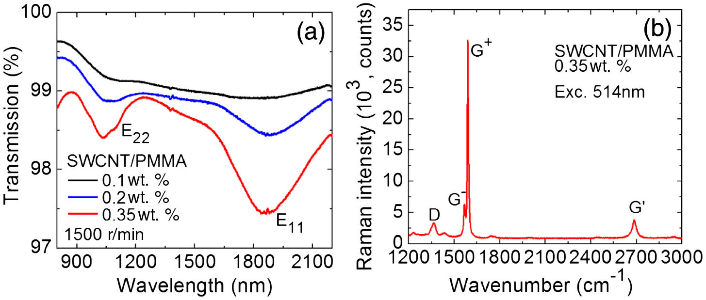
Fig. 1. (a) Small-signal internal transmission spectra of the SWCNT/PMMA films coated on quartz substrates with different concentrations of SWCNTs (0.1–0.35 wt. %); the spin-coating speed is 1500 r/min. (b) Raman spectrum of the 0.35 wt. % SWCNT/PMMA film coated on the surface of Tm:KLuW, λ exc = 514 nm
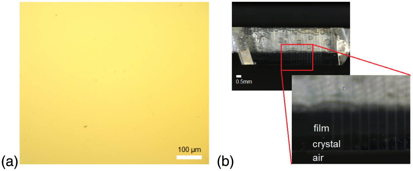
Fig. 2. (a) Optical microscope image of the surface of SWCNT/PMMA film (200 ×
Fig. 3. Confocal laser microscopy of a polished end-face of the fs-DLW Tm:KLuW surface channel WGs with cladding diameters of (a) 60 μm and (b) 50 μm, transmission mode, polarized light (P | | N p λ = 405 nm
Fig. 4. Confocal laser microscope images (top view) of the central part of the half-ring cladding fs-DLW surface WGs in Tm:KLuW: (a), (b) transmission mode, polarized light (P | | N g λ = 405 nm P | | N g A | | N m λ = 488 nm
Fig. 5. μ ∼ 907 cm − 1 cm − 1 g ( m m ) g N m
Fig. 6. (a) Scheme of the PQS fs-DLW Tm:KLuW surface WG laser: ND, gradient neutral density filter, PM, pump mirror, WG, waveguide, OC, output coupler, F, cutoff filter. (b) Photograph of the Ti:sapphire pumped WG showing blue upconversion luminescence.
Fig. 7. Input–output dependences for CW fs-DLW Tm:KLuW surface channel WG lasers with (a) 60 μm and (b) 50 μm cladding, η E | | N m
Fig. 8. Typical laser emission spectra of CW fs-DLW Tm:KLuW surface channel WG lasers with (a) 60 μm and (b) 50 μm cladding (measured at maximum P abs 4 ). The laser polarization is E | | N m
Fig. 9. Modified Caird analysis for 60 and 50 μm cladding CW fs-DLW Tm:KLuW surface channel WG lasers (symbols: experimental data; lines: their linear fits).
Fig. 10. Spatial near-field beam profiles of the output laser mode from the CW fs-DLW Tm:KLuW surface channel WG lasers with (a), (c) 60 μm and (b), (d) 50 μm cladding, T OC = 30 % P abs = 0.4 W N m N p
Fig. 11. Simulated fundamental mode for (a) 60 μm and (b) 50 μm WG. The DLW tracks and the crystal surface are indicated by red color. The assumed refractive index change at DLW tracks is − 0.01 + 0.0017 i
Fig. 12. fs-DLW Tm:KLuW surface channel WG lasers PQS by evanescent-field coupling with SWCNT-SA: (a) input–output dependences, η P abs E | | N m
Fig. 13. Pulse characteristics of fs-DLW Tm:KLuW surface channel WG lasers PQS by evanescent-field coupling with SWCNT-SA: (a) pulse duration, (b) PRF, (c) pulse energy, and (d) peak power. T OC = 30 %
Fig. 14. Oscilloscope traces of (a), (b) the typical pulse trains and (c) the corresponding single Q T OC = 30 % P abs = 0.5 W
|
Table 1. Pulse Characteristics of the fs-DLW Tm:KLuW Surface Channel Waveguide Lasers PQS by Evanescent-Field Coupling with SWCNTs


Set citation alerts for the article
Please enter your email address

© Copyright 2018-2021 | Chinese Laser Press. All Rights Reserved 沪ICP备15018463号-20