
Zhiwei Guo, Yang Long, Haitao Jiang, Jie Ren, Hong Chen. Anomalous unidirectional excitation of high-k hyperbolic modes using all-electric metasources[J]. Advanced Photonics, 2021, 3(3): 036001
- Advanced Photonics
- Vol. 3, Issue 3, 036001 (2021)
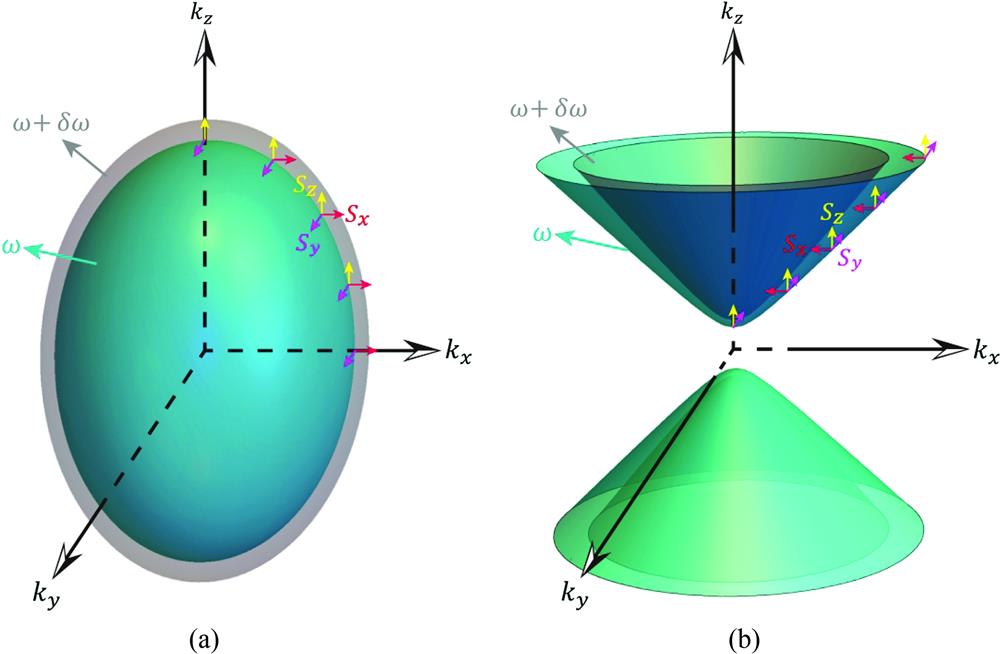
Fig. 1. Various 3D IFCs for (a) a closed ellipsoid and (b) an open hyperboloid when the frequency increases from
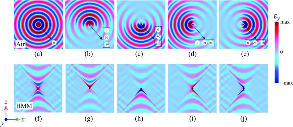
Fig. 2. (a) Radiation patterns for a simple point dipole in air, where the EM waves can propagate along all directions. (b)–(e) Unidirectional propagation from the Huygens metasource in air. (f) Radiation patterns for a simple point dipole in HMM, where the EM waves propagate mainly along the four channels with high-
Fig. 3. The
Fig. 4. (a) Schematic of a TL-based HMM structure with
Fig. 5. (a) Simulated point dipole radiation patterns in the circuit-based normal medium. The EM waves can propagate along all directions. (b)–(e) Unidirectional propagation of the Huygens metasources in a circuit-based normal medium. Panels (f)–(j) correspond, respectively, to (a)–(e) but for the simulated radiation patterns in the circuit-based HMM. Panels (k)–(o) correspond, respectively, to (a)–(e) but for the measured radiation patterns in the circuit-based HMM.
Fig. 6. (a), (b) Structure and related anisotropic 2D-circuit model of the TL-based DPS medium. Panels (c) and (d) are similar to (a) and (b) but for MNG media. Here,
Fig. 7. Schematics of (a) anomalous PSHE in an HMM waveguide and (b) normal PSHE in a DPS waveguide. A source with specific handedness excites only a single-guided mode with a specific propagation direction. Anomalous unidirectional excitation occurs in the HMM waveguide. For a counterclockwise-spin metasource, only the guided modes that propagate from right to left and left to right are excited in the (c) HMM and (d) DPS waveguides, respectively. However, for a clockwise-spin metasource, only the guided modes that propagate from left to right and right to left are excited in the (e) HMM and (f) DPS waveguides, respectively.
Fig. 8. (a) Experimental schematic of a circuit-based hyperbolic waveguide. Measured near-field distributions of

Set citation alerts for the article
Please enter your email address
© Copyright 2018-2021 | Chinese Laser Press. All Rights Reserved 沪ICP备15018463号-20