
Hong Chen, Ziyao Lyu, Changshun Wang, "Tunable polarization holographic gratings obtained by varying the ratio of intensities of the recording beams," Photonics Res. 12, 749 (2024)
- Photonics Research
- Vol. 12, Issue 4, 749 (2024)
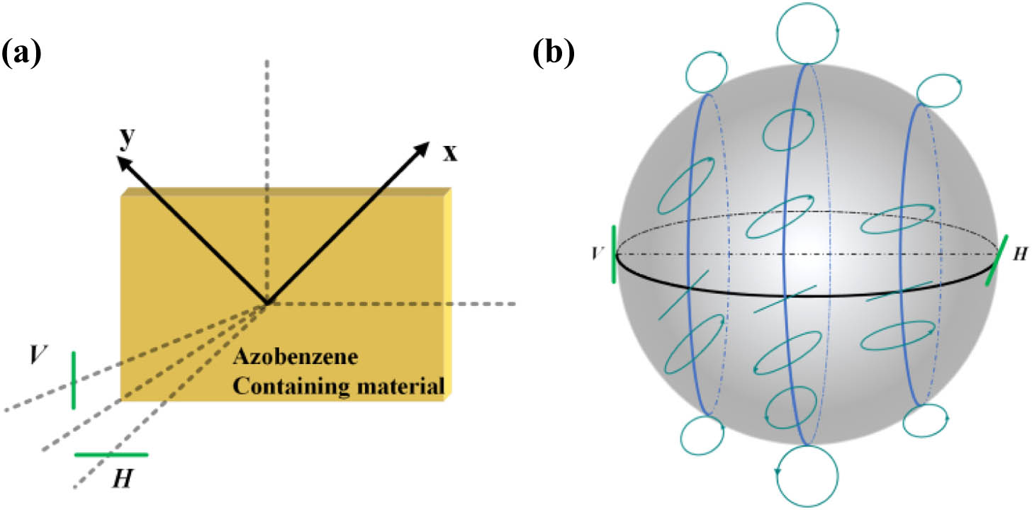
Fig. 1. Recording process of polarization holographic grating and Poincaré representation of the resultant polarization states E
![Absorption spectrum and molecular structure of self-assembled azobenzene liquid crystal film [33].](/richHtml/prj/2024/12/4/749/img_002.jpg)
Fig. 2. Absorption spectrum and molecular structure of self-assembled azobenzene liquid crystal film [33].
Fig. 3. Setup of intensity-based polarization manipulation by tunable polarization holographic grating (M, mirror; BS, beam splitter; P, polarizer; H, half-wave plate; Att, attenuator; Q, quarter-wave plate).
Fig. 4. Temporal behavior of the ± 1 V H ± 1 V H
Fig. 5. Polarization manipulation of the tunable polarization holographic grating with the incident beam of LCP [blue triangle dashed line, + 1 − 1 V H
Fig. 6. Polarization modulation of the tunable polarized holographic grating with the incident beam of RCP [blue triangle dashed line, + 1 − 1 V H


Set citation alerts for the article
Please enter your email address

© Copyright 2018-2021 | Chinese Laser Press. All Rights Reserved 沪ICP备15018463号-20