1State Key Laboratory of Advanced Optical Communication Systems and Networks, School of Physics and Astronomy, Shanghai Jiao Tong University, Shanghai 200240, China
2State Key Laboratory of Space-Ground Integrated Information Technology, Beijing Institute of Satellite Information Engineering, Beijing 100095, China
Hong Chen, Ziyao Lyu, Changshun Wang, "Tunable polarization holographic gratings obtained by varying the ratio of intensities of the recording beams," Photonics Res. 12, 749 (2024)
Copy Citation Text
【AIGC One Sentence Reading】:A tunable polarization holographic grating, recorded on an azobenzene film with asymmetric light intensities, allows active manipulation of diffracted light polarization from linear to circular.
【AIGC Short Abstract】:Polarization holography, known for its polarization modulation, finds use in various fields. We've designed a tunable polarization holographic grating using Jones matrices, achieving intensity-based polarization control. Recorded on an azobenzene liquid-crystalline film using coherent, orthogonally polarized beams with asymmetric intensities, this grating allows active manipulation of diffracted light from linear to circular polarization, enhancing light manipulation and holography.
Note: This section is automatically generated by AI . The website and platform operators shall not be liable for any commercial or legal consequences arising from your use of AI generated content on this website. Please be aware of this.
Abstract
Polarization holography has been extensively applied in many fields, such as optical science, metrology, and biochemistry, due to its property of polarization modulation. However, the modulated polarization state of diffracted light corresponds strictly to that of incident light one by one. Here, a kind of tunable polarization holographic grating has been designed in terms of Jones matrices, and intensity-based polarization manipulation has been realized experimentally. The proposed tunable polarization holographic grating is recorded on an azobenzene liquid-crystalline film by a pair of coherent light beams with orthogonal polarization states and asymmetrically controlled intensities. It is found that the diffracted light can be actively manipulated from linearly to circularly polarized based on the light intensity of the recording holographic field when the polarization state of incident light keeps constant. Our work could enrich the field of light manipulation and holography.
1. INTRODUCTION
Polarization [1,2] is defined as the description of the vibration of the electric field, which can be linear, circular, or elliptical. This property of light has found widespread application in optical systems, such as optical communication [3,4], optical storage [5–8], and optical science [9,10]. Specifically, a scheme for achieving pseudo-polarization-division-multiplexing of four states was successfully demonstrated through the manipulation of four linearly polarized data channels operating at the same wavelength to explore the use of polarization freedom for enhancing both the capacity and spectral efficiency of fiber-based communication systems [3]. A compact polarization camera capable of capturing full-Stokes polarization information was developed using metasurface technology, eliminating the need for conventional polarization optics and mechanical components, thereby streamlining the polarization imaging process [10]. Elliptically polarized light, in particular, has been shown to induce asymmetric photolysis of racemic organic substrates, enabling the generation of measurable enantiomers [11]. Additionally, it broadens the dimension of multi-photon process research, allowing for the study of long quantum orbitals in strong field atomic systems [12] and the control of molecular direction [13].
As it is crucial to control the polarization state of light, various methods have been proposed to fully leverage the potential of polarization in these applications. A polarization control system utilizing fiber optic squeezers was proposed, characterized by slow response times and potential mechanical vibration instability [14]. Subsequently, a polarization control method based on piezoelectric actuator (PZT) charge control was realized, which requires a complex electrical control system and suffers from long response time [15]. In addition, a Faraday rotator constructed from magneto-optical crystals was presented to control light polarization with a response time of only 150 μs [16]. Polarization modulation utilizing nonlinear effects, including stimulated Brillouin scattering [17,18], four-wave mixing [19], and Raman scattering [20], can even offer response time as short as picoseconds or femtoseconds.
For enhancing polarization stability, grating-based all-optical modulation is a dependable and stable method for achieving polarization control. Polarization holographic grating [21–23] is a type of grating that has been extensively studied. Polarization holographic gratings, in particular, are capable of recording the polarization state of waves in polarization-sensitive materials [24–26] using two writing beams with perpendicular polarization directions [27]. This results in a periodic spatial modulation of photoinduced anisotropy in polarization-sensitive materials [28–30], manifesting as a polarization modulation of the light passing through the grating. In recent years, significant progress has been made in this area. For example, Lyu et al. achieved polarization control by recording tunable polarization gratings [31,32] on azo liquid crystal thin films [33]. Then, Lyu et al. further implemented a controllable beam splitter based on asymmetric polarization holography [34]. Besides, a study on the polarization holographic properties of TI/PMMA polymer materials was conducted by Liu et al. under linearly polarized light [25]. However, it is important to note that for recorded polarized grating, the polarization state of the diffracted light is uniquely determined by the incident beam. For example, for polarization gratings recorded with orthogonal linear polarization waves, when the polarization state of the probe light is horizontal, the polarization of the diffracted light can only be vertical.
Sign up for Photonics Research TOC. Get the latest issue of Photonics Research delivered right to you!Sign up now
In this paper, we proposed a kind of tunable polarization holographic grating based on the theoretical analysis of Jones matrices and recorded the designed holographic grating on an azobenzene liquid-crystalline film using two orthogonally linearly polarized light beams with asymmetric intensities. When the polarization state of the probe light keeps constant, the diffracted light can be modulated actively from linearly to circularly polarized as the light intensity ratio of the two recording beams is controlled between 13:1 and 1:10. This intensity-based polarization manipulation is attributed to the trans-cis isomerization and photoinduced birefringence of azobenzene liquid crystals. This work could hold great promise for a wide range of applications in the field of optics and photonics.
2. THEORY ANALYSIS
Considering an azobenzene containing material, molecules are randomly oriented in all directions before illumination. Upon exposure to linearly polarized light, the stable trans-formation molecules will undergo a trans-cis isomerization process, leading to the formation of unstable cis-formation molecules that subsequently revert back to the trans-formation. This photo-induced molecular rotation is dependent on the polarization direction of the incident light, as well as , where is the angle between the molecule orientation and the polarization direction of the linearly incident light. Consequently, molecules initially arranged along the polarization direction of light are more likely to absorb linearly polarized light and rotate. This absorption-rotation cycle will continue until the orientation of most molecules becomes perpendicular to the polarization direction of the incident beam. At this point, a state of equilibrium is reached, where most molecules are oriented perpendicular to the direction of the linearly polarized light, resulting in the development of photo-induced anisotropy . This mechanism of photoinduced anisotropy formation was first proposed by Todorov et al. [21].
We define the values of refractive index parallel and perpendicular to the polarization direction of incident light as and , respectively. Then, it can be deduced that . After exposure, the refractive index value where is the refractive index value before exposure, and and are the light response coefficients of the material in the parallel and perpendicular directions, respectively. is the semi-major axis, and is the semi-minor axis. We denote With the polarization azimuth angle , the rotation matrix is The Stokes parameters of the polarization holographic field are This definition of the Stokes parameters is only applicable for totally polarized light. Therefore, the change in refractive index can be further expressed as The Jones matrix of the polarization holographic grating is where is the thickness of the polarization holographic grating and is the wavelength of the incident light.
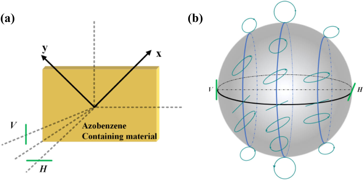
We consider two mutually orthogonally linearly polarized lights with different intensities as recording light [Fig. 1(a)], where is the light intensity ratio of the recording beams and is the phase between the two recording waves. The total field As changes, the total field will cover every longitude on the Poincaré sphere, as shown in blue lines in Fig. 1(b). Combining Eqs. (4), (6), and (8), we obtain the tunable polarized holographic grating expressed with the Jones matrix, where
If we assume that the read-out beam is circularly polarized, Then the diffracted beam
The variation of in Eq. (8) results in distinct , indicating the feasibility of a polarization holographic grating that can be tuned. From Eq. (12), we can control the polarization of the diffracted light by modulating the parameter in the following part.
Figure 1.Recording process of polarization holographic grating and Poincaré representation of the resultant polarization states .
The sample we utilized is a self-assembled azobenzene liquid crystal film composed of a poly ionic liquid (PIL, Sigma-Aldrich, JRD1685) and methyl orange dye (MO, Sigma-Aldrich, 114510) [33]. This sample is enclosed between two layers of glass substrates, forming a sandwich structure. To prepare the ionic self-assembly complex, 2 mg/mL aqueous solution of PIL was added dropwise to an aqueous solution of MO with the same concentration, maintaining a 1:1 molar charge ratio. The resulting complex was then precipitated, filtered, and washed multiple times with doubly distilled water to eliminate any residual salts and unreacted precursors. The dried complex was subsequently subjected to vacuum drying at 60°C for a duration of 12 h. The powder obtained from the complex exhibited a melting point of approximately 180°C, with noticeable Schlieren textures appearing during the cooling phase. The presence of pronounced Schlieren textures indicated a high degree of orientational order within the complex. Due to statistical redirection and photo-induced trans-cis isomerization, the azobenzene molecules ultimately align perpendicularly to the polarization direction of the incident linearly polarized light. The absorption spectrum and molecular structure of the self-assembled azobenzene liquid crystal film are shown in Fig. 2. The thickness of the thin film is 10 μm, measured by the Alpha-step D-600. While two orthogonal linearly polarized lights irradiated on the film simultaneously, the polarization states of the waves were periodically arranged (examples are shown by the blue lines in Fig. 1), resulting in a periodic orientation of molecules. Then a polarized holographic grating is formed due to photo-induced birefringence.
Figure 2.Absorption spectrum and molecular structure of self-assembled azobenzene liquid crystal film [33].
All-optical intensity-based polarization manipulation by a tunable polarized holographic grating setup is depicted in Fig. 3. A laser with a wavelength of 532 nm (CW Nd:YAG, ) was directly emitted on the beam splitter (BS) through the mirror , where it was split into two beams with a light intensity ratio of 1:13. In one arm, the beam was adjusted to be the linear polarization state of (or ), which is horizontal (or vertical) to the surface (green line in Fig. 1) by passing through the mirror , polarizer , and half-wave plate . The intensity of the beam was set by the attenuator Att. However, in another arm, the beam passed through the mirror , polarizer , and half-wave plate , resulting in a wave (or ) with a polarization state vertical (or horizontal) to the surface (green line in Fig. 1). Both waves were irradiated on the same point of sample at a small angle of 5°, enabling the formation of a tunable polarization holographic grating. A 633 nm laser (CW He-Ne) was used as the detection light. The left-handed circular polarization (LCP) and right-handed circular polarization (RCP) of the wave can be obtained by the quarter-wave plate . A free space polarimeter (Thorlabs, PAX5710VIS-T) was utilized to analyze the polarization state of the diffracted light.
Figure 3.Setup of intensity-based polarization manipulation by tunable polarization holographic grating (M, mirror; BS, beam splitter; P, polarizer; H, half-wave plate; Att, attenuator; Q, quarter-wave plate).
For realizing a tunable polarization holographic grating, we can control the intensity of the recording beams and . Specifically, the intensity of the recording wave is gradually reduced from 13 to 1 mW while the recording wave is maintained at a constant of 1 mW. Subsequently, the intensity of the writing light is fixed at 1 mW, while the intensity of is gradually increased from 1 to 10 mW. When the two recording beams are simultaneously irradiated on the same point of the sample (532 nm on), the dynamics of st-order diffraction efficiency exhibits a two-stage growth process, namely a fast and slow process, which follows the double exponential function [35]: where is the diffraction efficiency. and represent the rising rates of fast and slow processes, respectively. and represent the time constants of fast and slow processes, respectively. Taking an example of the recording beams and with an intensity-ratio of 1:1 in Fig. 4, the st-order diffraction efficiency rapidly increases during the first 10 s with the LCP incident beam, owing to the significant orientation response of a large number of azobenzene molecules. Subsequently, the diffraction efficiency of st-order slowly increases with the LCP incident beam, which is attributed to the orientation saturation of azobenzene molecules. After the pump lights are turned off (532 nm off), the diffraction efficiency can be maintained at 0.7% for a long time, indicating the long-term optical storage characteristics of azobenzene molecules. This is because the photo-induced oriented azobenzene molecules remain stably present in the liquid crystal aggregation phase. The red line in Fig. 4 represents the fitting curve with parameters , , , and . The impact of diverse intensity-ratios of the recording beams on the diffraction efficiency of st-order with LCP or RCP incident light is illustrated in the inset of Fig. 4. The results indicate that there is no more than a 0.15 variation in st-order diffraction efficiency across different intensity-ratios of recording lights. The diffraction efficiency is observed to be at its minimum when the intensities of the recording lights of and are equivalent. This can be attributed to the fact that the overall pump light is minimum, leading to the fewest numbers of orientations of azobenzene molecules compared to the other situations. The diffraction efficiency is much higher when the intensities are in a 1:10 ratio rather than in a 13:1 ratio, attributed to the higher intensity causing an intensified disorderly motion of azobenzene molecules. In this way, a fairly stable tunable polarization holographic grating can be achieved. It should be noted that when two orthogonally linearly polarized writing beams are irradiated onto an azobenzene-containing material, two types of photo induced gratings, birefringence and surface relief gratings, are usually formed on the film [36,37]. In the case where the azobenzene film is enclosed between two glass substrates to form a sandwich structure, the formation of surface relief gratings can be effectively suppressed [38]. Therefore, a pure polarization holographic grating without surface relief structure is written on the azobenzene polymer film with two orthogonal linearly polarized 532 nm beams, which is confirmed by atomic force microscopy.
Figure 4.Temporal behavior of the st-order diffraction efficiency with the incident beam of LCP under the intensity-ratio of the recording beams and of 1:1 (blue, experiment result; red, fitting curve; inset, st-order diffraction efficiency with the incident beams of LCP and RCP under the different intensity-ratios of the recording beams and ).
In the case of the incident beam being LCP, the polarization manipulation of the diffracted st based on the tunable polarization holographic grating is demonstrated in Fig. 5. The st-order and st-order diffraction lights with the incident beam of LCP are denoted by the blue triangle and red cycle dashed lines, respectively. Notably, both the ellipticities of st-order and st-order diffraction waves exhibit positive values from 0 to , indicating a right-handed polarization state output. When the intensity-ratio of the recording beams is 1:1, the polarization modulation is identical to that of ordinary polarization holography [33]. In detail, the st-order and st-order diffracted lights are both RCP [Fig. 5(b)]. As the intensity-ratios of and writing beams are asymmetrical, the ellipticity of st-order and st-order diffracted waves displays a different “”-shaped trend, marked by an initial increase followed by a decrease repeatedly. The intensity of the writing light, denoted as , remains constant at 1 mW, while the intensity of the writing beam, denoted as , is gradually decreased from 13 mW to 1 mW. During this process, the polarization state of the st-order and st-order diffracted waves transitions from elliptical polarization [as examples shown in inset of Figs. 5(a) and 5(d)] to RCP with varying ellipticity, except in the case where the intensity of is 7 mW and the st-order diffraction is linearly polarized [Fig. 5(e)]. Furthermore, as the intensity of the recording wave changes from 1 mW to 10 mW while maintaining the recording wave at a constant 1 mW, the polarization states of the st-order diffracted waves change from RCP to right-handed elliptical polarization [as an example shown in inset of Fig. 5(c)], and eventually to linear polarization [Fig. 5(e)]. On the other hand, the polarization state of the st-order diffracted light only undergoes a transition from RCP to right-handed elliptical polarization. Remarkably, the st-order diffracted light is linearly polarized with an ellipticity equal to zero at the intensity ratio of and . Thus, by adjusting the intensity of recording beams and , linear polarization, right-handed elliptical polarization, and right-handed circular polarization can be obtained with the polarization state of the probe light of LCP.
Figure 5.Polarization manipulation of the tunable polarization holographic grating with the incident beam of LCP [blue triangle dashed line, st-order polarization modulation; red cycle dashed line, st-order polarization modulation; insets (a)–(e) are polarization states of diffracted light based on the different intensity-ratios of recording beams and ].
The dependence of polarization modulation of the RCP incident beam on the tunable polarization holographic grating is also investigated, as illustrated in Fig. 6. The blue triangle dashed line denotes the st-order diffraction light for the incident beam of RCP, while the red cycle dashed line represents st-order diffraction light for the same. It is noteworthy that the diffraction pattern for the RCP incident beam is distinct from that of the LCP incident beam, wherein all the diffracted beams are left-handed due to negative ellipticity. By adjusting the intensity of the recording beams and , different polarization states of the diffracted wave, including linear, left-handed elliptical, and left-handed circular polarization, can be achieved. As shown in the inset of Figs. 6(a) and 6(b), the linearly polarized wave can be obtained in the st-order diffracted light when the intensity ratio of and is 13:1 and 1:10. The polarization states of diffracted light of both st-order and st-order are identical with the equal intensity of and , yielding left-circular polarization [Fig. 6(d)]. For other cases, st-order diffracted lights are elliptically polarized with different ellipticity [Figs. 6(c) and 6(e)]. However, when the intensity ratio of and deviates from unity, the trend of ellipticity variation follows a “”-shaped pattern, with an initial decrease followed by an increase from the ratio of to , irrespective of the st-order or st-order diffracted light. As such, the range of ellipticity values spans from to 0.
Figure 6.Polarization modulation of the tunable polarized holographic grating with the incident beam of RCP [blue triangle dashed line, st-order polarization modulation; red cycle dashed line, st-order polarization modulation; insets (a)–(e) are the polarization states of diffracted light based on the different intensity-ratios of recording beams and ].
As mentioned, the experimental results well verify the theoretical analysis, demonstrating the successful implementation of intensity-based polarization manipulation through a tunable polarization holographic grating. This achievement significantly contributes to the advancement of optical manipulation and holography, establishing a solid foundation for the practical application of this methodology.
5. CONCLUSION
In summary, we have designed and realized a novel class of tunable polarization holographic grating on an azobenzene liquid-crystalline film, based on Jones matrices. This was achieved by utilizing two recording beams that were orthogonally polarized with asymmetric intensities. The recording process exhibited a two-stage diffraction efficiency, characterized by fast and slow processes. The resulting tunable polarization holographic grating was found to be capable of modulating the polarization state of the incident light based on the intensity, within an ellipticity range of to , for a given incident circular polarization of left-handed circularly polarized and right-handed circularly polarized light. Furthermore, the control of the incident beam of LCP or RCP makes it possible to achieve right-handed and left-handed waves, respectively. This experiment represents a significant advancement in the field of polarization manipulation techniques and has the potential to expand the range of applications for polarization holographic gratings.
References
[1] M. Born, E. Wolf. Principles of Optics(1980).
[2] R. M. A. Azzam, N. M. Bashara. Ellipsometry and Polarized Light(1977).
Hong Chen, Ziyao Lyu, Changshun Wang, "Tunable polarization holographic gratings obtained by varying the ratio of intensities of the recording beams," Photonics Res. 12, 749 (2024)
 AI Video Guide
  AI Picture Guide
 AI One Sentence