• Journal of Infrared and Millimeter Waves
  • Vol. 41, Issue 3, 557 (2022)
Shou-Xi XU1、*, Jie YANG1、2, Hu WANG3, Zhi-Hui GENG1, and Rui ZHANG1
Author Affiliations
  • 1Key Laboratory of High Power Microwave Sources and Technologies,Aerospace Information Research Institute,Chinese Academy of Sciences,Beijing 101400,China
  • 2University of Chinese Academy of Sciences,Beijing 100049,China
  • 3Hisense Mobile Communication Technology Co.,Ltd.Qingdao 266555,China
  • show less
    DOI: 10.11972/j.issn.1001-9014.2022.03.006 Cite this Article
    Shou-Xi XU, Jie YANG, Hu WANG, Zhi-Hui GENG, Rui ZHANG. Design of a quasi-optical mode converter for a 170 GHz gyrotron[J]. Journal of Infrared and Millimeter Waves, 2022, 41(3): 557 Copy Citation Text show less
    Relative power of each mode along the length of the TE31,8 launcher
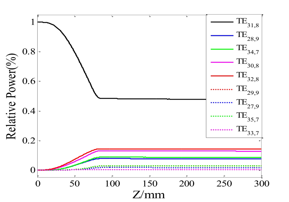
    Fig. 1. Relative power of each mode along the length of the TE31,8 launcher
    The wall deformations of the launcher
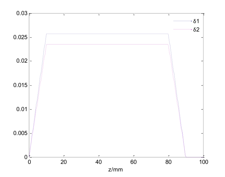
    Fig. 2. The wall deformations of the launcher
    Azimuth bunching with only δ1=0
    Fig. 3. Azimuth bunching with only δ1=0
    Longitudinal bunching with onlyδ2=0
    Fig. 4. Longitudinal bunching with onlyδ2=0
    Electric field distribution on the unrolled waveguide wall (a) 3D plot (b) intensity contour map
    Fig. 5. Electric field distribution on the unrolled waveguide wall (a) 3D plot (b) intensity contour map
    The schematic of the mirror system
    Fig. 6. The schematic of the mirror system
    Electric field distribution at the first mirror
    Fig. 7. Electric field distribution at the first mirror
    Electric field distribution at the second mirror
    Fig. 8. Electric field distribution at the second mirror
    Electric field distribution at the third mirror
    Fig. 9. Electric field distribution at the third mirror
    Electric field distribution at the fourth mirror
    Fig. 10. Electric field distribution at the fourth mirror
    Electric field distribution on the output window
    Fig. 11. Electric field distribution on the output window
    Electric field 3D distribution on the output window
    Fig. 12. Electric field 3D distribution on the output window
    Azimuthal bunching
    Axial bunchingTE29,9(1/36)TE32,8(1/9)TE35,7(1/36)
    TE28,9(1/9)TE31,8(4/9)TE34,7(1/9)
    TE27,9(1/36)TE30,8(1/9)TE33,7(1/36)
    Table 1. Nine TE modes and their relative powers to form a Gaussian-like distribution
    Mirror numberMirror center(mm)

    Mirror

    size(mm)

    Focus length(mm)
    M1(10,60,0)150*100

    Fx=50

    Fz=1700

    M2(-10,-80,60)140*100

    Fx=110

    Fz=365

    M3(0,60,130)120*100

    Fx=60

    Fz=1200

    M4(0,-90,235)80*80

    Fx=379

    Fz=210

    M5(0,80,235)60*60
    Table 2. Parameters of mirrors
    Collected normalized powerPower transmission efficiency(%)
    M10.992997.93
    M20.972399.23
    M30.964899.23
    M40.957999.86
    Output window0.9566
    Table 3. Performance of the mirror system
    Shou-Xi XU, Jie YANG, Hu WANG, Zhi-Hui GENG, Rui ZHANG. Design of a quasi-optical mode converter for a 170 GHz gyrotron[J]. Journal of Infrared and Millimeter Waves, 2022, 41(3): 557
    Download Citation