1Key Laboratory of High Power Microwave Sources and Technologies,Aerospace Information Research Institute,Chinese Academy of Sciences,Beijing 101400,China
2University of Chinese Academy of Sciences,Beijing 100049,China
3Hisense Mobile Communication Technology Co.,Ltd.Qingdao 266555,China
Shou-Xi XU, Jie YANG, Hu WANG, Zhi-Hui GENG, Rui ZHANG. Design of a quasi-optical mode converter for a 170 GHz gyrotron[J]. Journal of Infrared and Millimeter Waves, 2022, 41(3): 557
Copy Citation Text
A high efficiency Denisov-type quasi-optical mode converter for a 170 GHzmode gyrotron is presented. The mode converter comprises a dimpled-wall launcher and a mirror system. Based on the coupled mode theory, the advanced launcher having two stages of perturbations is investigated. A mirror system of the converter is optimized and designed by using the vector diffraction theory. Simulation results show that the good Gaussian mode is converted from the circular waveguide mode and the mode conversion efficiency of a quasi-optical mode converter is 93.7%.
Gyrotrons are fast wave devices which can generate a megawatt power level in the continuous wave(CW)operation at frequencies of a 110~170 GHz. They have been widely used in Electron Cyclotron Resonance Heating(ECRH)at the International Thermonuclear Experimental Reactor(ITER),plasma diagnostics and material processing[1-5]. In order to increase the output power,the gyrotrons usually operate in the high order transverse electric mode. However,the RF power is not suitable for the direct use due to the radiation polarization. So,the high order output modes of the gyrotron must be converted to linearly polarized Gaussian modes. Quasi-optical(QO)mode converter has proven to be high conversion efficiency and low loss method of transmission. It is one of the crucial components for CW operation of high power gyrotrons[6-7]. The converter consists of a cylindrical waveguide section with a radiation launcher followed by a mirror system. The advantages of the quasi-optical mode converter are:
1)The converter separates the electromagnetic wave from the electron beam.
2)This quasi-optical system can produce linearly polarized Gaussian beams which is appropriate for various applications.
According to the different launcher type,the QO mode converter is classified into Vlasov-type and Denisov-type. A Vlasov-type converter proposed by Vlasov has a simple structure,but it has high diffraction loss(15%-20%)which cannot be accepted for high-power gyrotrons[8-10]. In order to reduce diffraction losses and the dimensions of focusing mirror system,the advanced launcher has been proposed by Denisov et al.[11]. The launcher uses an irregular waveguide section which bunches the radiation into Gaussian beams.
In this paper,study of Denisov-type QO mode converter for a 170 GHz gyrotron is described. A QO mode converter with a Denisov-type launcher and four mirrors is investigated. The converter is used to transform the waveguide mode produced by a 170 GHz gyrotron oscillator to a Gaussian beam.
1 Design of pre-bunching launcher
The Denisov-type launcher consists of a pre-bunching section with a helical-cut aperture. The purpose of the launcher is to obtain a mode mixture generating a Gaussian beam.
Azimuthal bunching
Axial bunching
(1/36)
(1/9)
(1/36)
(1/9)
(4/9)
(1/9)
(1/36)
(1/9)
(1/36)
Table 1. Nine TE modes and their relative powers to form a Gaussian-like distribution
A Gaussian beam can be obtained by means of a superposition of nine specific waveguide modes with matched amplitudes and relative phases. The field distribution of a two-dimensional description can be approximated by equation(1)[12]
,
This function shows that the formation of a Gaussian beam requires interference with nine waveguide modes in the longitudinal and radial directions bunching. This should satisfy the following rules:
,
where m is the mode index,is the root of Bessel function’s derivate, is the cut length of the launcher, is the caustic radius. For the mode,we have ,the ratio of caustic()to cavity radius()is approximately 0.5. The modes necessary for the superposition are shown in Table I.
The launcher has a tapered dimpled-wall. The taper is used to avoid parasitic oscillations in the launcher. To excite the necessary modes,the inner wall has two stages of perturbations described by the following equation[13]:
,
where refers to the average radius,is the taper slope(),are the magnitudes of the disturbance which are optimized to form a Gaussian distribution. is an azimuthal angle. 、、、are defined as
,
,
,
.
Propagation in a slightly irregular waveguide surface disturbance can be described by a set of coupled wave equations. In general,the equations for coupling between forward-going propagating waves are given by
,
where TM mode is ignored,we consider only TE mode.
The coefficientis written as[14]
,
where is the root of Bessel function’s derivate.
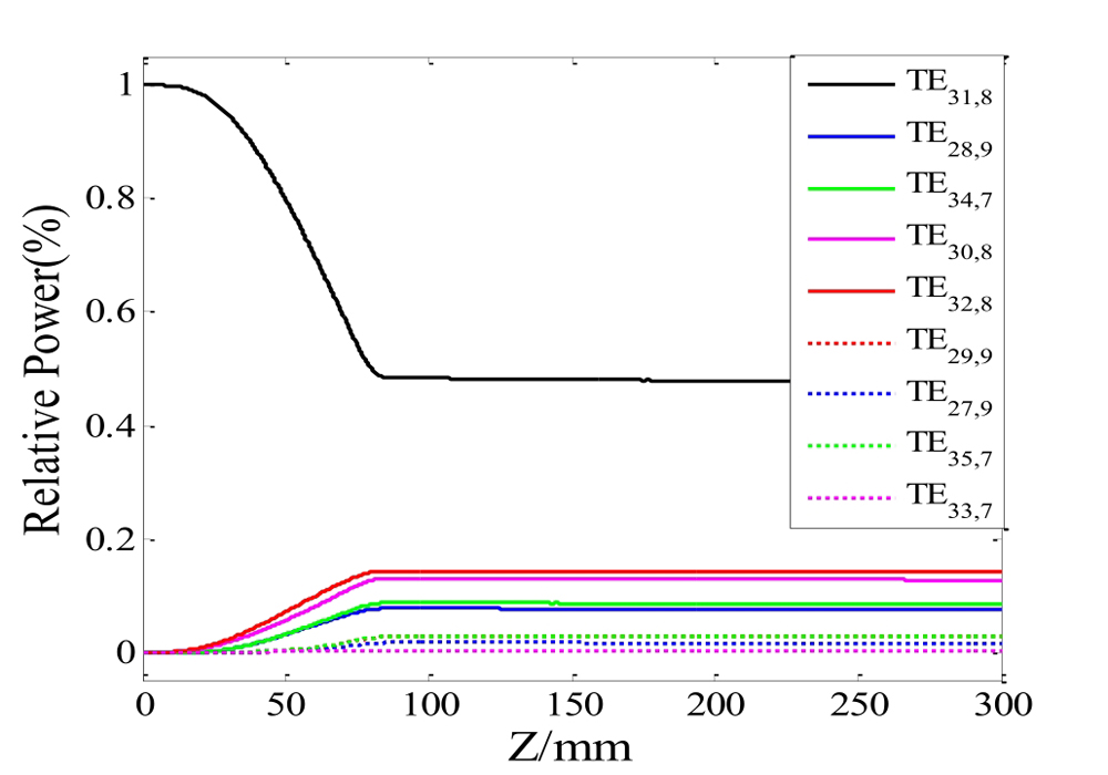
The design procedure for the launcher is performed in two steps. Firstly,the irregular waveguide mode converter is analyzed by using coupled mode theory. Secondly,the radiated fields are calculated from the waveguide cut using the vector diffraction integral. By optimizing the wall perturbation,a 170 GHz mode Denisov-type launcher is designed. The power distribution of each mode along the length of the converter is shown in Fig. 1. At the same time,the wall deformations are given in Fig. 2. From Fig. 1,we can see that a pure TE31,8 mode is injected. As the wave travels upwards along the z axis,the TE31,8 mode is coupled into eight satellite modes through the wall perturbations. The four satellite modesTE28,9,TE34,7(the two modes coupled with ,as shown in Fig. 3 azimuth bunching),TE32,8,TE30,8(the two modes coupled with,as shown in Fig. 4 longitudinal bunching)are strongly coupled from the TE31,8 mode. These four modes are then weakly coupled to the other four modesTE29,9,TE27,9,TE35,7,TE33,7. The electrical field on the unrolled waveguide wall calculated by coupled mode theory is shown in Fig. 3. It is obvious that the field intensity has been transformed from a uniform distribution to Gaussian distribution. The simulations show that the scalar Gaussian content is 98% at the aperture of the launcher. The field intensity at the edge of the aperture is much lower than that at the center of the beam spot. Thus,the field intensities on the cuts are very low(The cutline is indicated by a green line). After calculation and optimization,the cut length is 40 mm and the total length of the advanced launcher is 200 mm. The fields are radiated from the cut of the launcher and feed the mirror system.
Figure 1.Relative power of each mode along the length of the TE31,8 launcher
Radiated from the launcher,the electromagnetic wave is focused and reflected by the mirror system and travels upwards towards the output window. In the paper,four mirrors are designed by applying Gaussian optics theory. In rectangular coordinate systems,the mirror surface profiles are given by [15]
The first mirror is used to focus the divergent beam radiating from the launcher. The final three mirrors with different focal length in different directions shape the beam along one axis respectively. Figure 6 shows the arrangement of the whole mirror system. Starting from z = 0,the mirror M1,M2,M3,M4 are in the forward direction along the z axis,and the last mirror is the output window.
In the design,it is found that the size,center position,focal lengths and inclination angle of the mirrors have strong influence on the results. The central position and size of the mirror determine how much energy it can trap from the wave radiated by the upper mirror or the launcher,and its focal length determines the degree of beam bunching. If the focal length is too small or too large,a part of the energy will be emitted into the space and will not be intercepted by the lower mirror. The inclination angle mainly adjusts the propagation direction of the wave. The size of gyrotron output structure should also be considered in the design.
In the calculation,each reflector is considered as an ideal conductor mirror. The field on the first mirror is calculated by equation(11-12)[16]:
,
,
The field on the second mirror,third mirror and output window is calculated by equation(13-14):
,
.
The electric field distribution of each mirror is shown in Fig. 7 to Fig. 10. The field distribution of the output window plane is given in Fig. 11 and Fig. 12. The parameters of mirrors are listed in Table II. Table III gives the performance of the mirror system. As shown in Fig. 12,a Gaussian-like beam is obtained. The conversion efficiency of the converter is about 93.7%.
Figure 7.Electric field distribution at the first mirror
To further examine the Gaussian quality of the beam,the correlation coefficient of the radiation field to an ideal fundamental Gaussian mode(TEM00)is described:the scalar correlation coefficient and the vector correlation coefficient,which can be given as [16]
,
,
where represents the field distribution of the radiation field at the output window and an ideal fundamental Gaussian beam,respectively. Based on the above discussion,the scalar correlation coefficient is about 98%,and the vector correlation coefficient is more than 92%.
3 Conclusions
A Denisov-type quasi-optical mode converter has been designed to convert the mode at 170 GHz to a Gaussian beam. The converter consists of a dimpled-wall launcher and three focusing reflectors. Coupled mode theory is used to analyze the Denisov-type launcher. The reflectors,designed with geometric optics and vector diffraction theory,have smooth shaping surface. The structure parameters of the mode converter are obtained. The field distributions of the launcher,mirrors and output window are numerically simulated. The simulation results show that an efficiency of more than 93.7% has been achieved. The energy loss in the process of transmission and reflection is about 4.3%. Future work will further optimize the disturbance structure of the launcher and improve the quality of the Gaussian beam by adding a phase correction mirror. This work can bring guidance to the development and design of QO mode converter for a 170 GHz gyrotron.
[10] Hui-QI Bian, Chao-Hai Du, Shi Pan et al. Design and analysis of broadband quasi-optical mode converter with a Denisov launcher. Journal of Infrared Millimeter Waves, 39, 567-575(2020).
[12] M Thumm, R A Cairns, A Phelps. D.R. Modes and mode conversion in microwave devices in Generation and Application of High Power Microwaves. Eds. Bristol, 121-171(1997).
[15] Bin Wang, Yun-long Liu, Hu Wang et al. Denisov-type quasi-optical mode converter for high-order asymmetric volume mode gyrotron. High Power Laser and Particle Beams, 28, 0730051-0730058(2016).
Shou-Xi XU, Jie YANG, Hu WANG, Zhi-Hui GENG, Rui ZHANG. Design of a quasi-optical mode converter for a 170 GHz gyrotron[J]. Journal of Infrared and Millimeter Waves, 2022, 41(3): 557