
Zhao-Hui MA, Jing-Yang WANG, Han-Dan JING, Fan LIU, Wei-Dong HU, Xin LYU. Millimeter wave security imaging based on single-channel MIMO radar[J]. Journal of Infrared and Millimeter Waves, 2020, 39(6): 709
- Journal of Infrared and Millimeter Waves
- Vol. 39, Issue 6, 709 (2020)
Abstract
Keywords
Introduction
Millimeter wave (mmW) has the characteristics of transparency to fiber, non-ionization to biological tissue, and relatively higher resolution compared with microwave, which makes mmW a promising frequency band for security imaging [
To tackle the above issues, the sparse array theory has been widely studied as a promising solution for system design [
Considering the above discussions, CDM is a promising technique for the low-cost and low-complexity radar, which is therefore exploited to develop the single-channel mmW MIMO security imaging radar system in this paper. To enhance the single-channel MIMO radar’s performance, a de-multiplex code with the maximum code diversity gain as well as low shift-phase correlation is designed based on mismatched filter theory. Finally, simulation and experimental results are provided to verify the correctness and validity of the proposed methods.
1 Single-channel MIMO radar based on dual-CDM technique
1.1 Architecture of single-channel MIMO radar
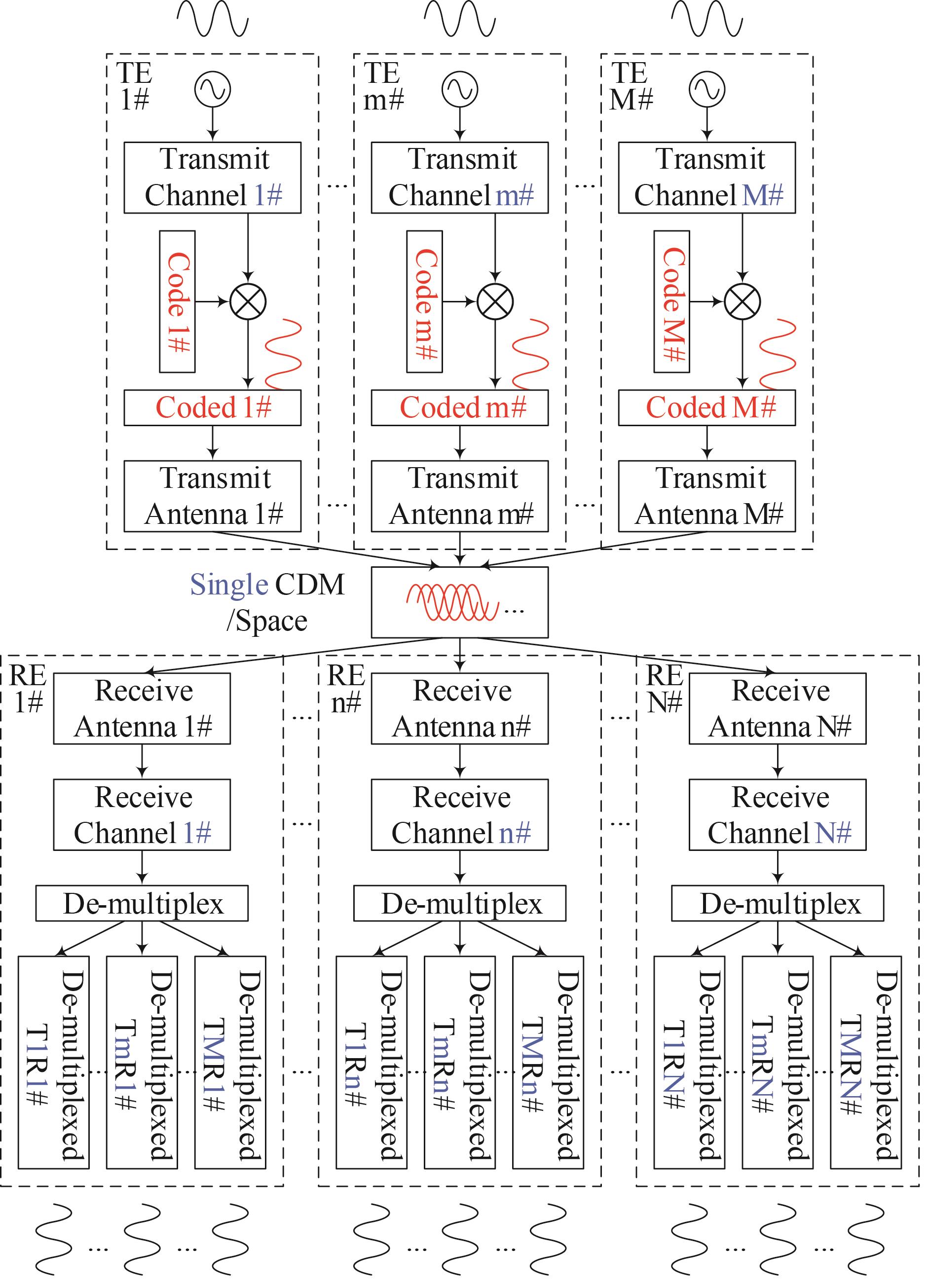
Featured with the multi-antenna structure in both the transmit and receive array, the traditional MIMO radar usually calls for multiple channels containing full digital transceiver including up/down-converter, DAC/ADC, memory and digital interface. As shown in Fig. 1, a transmit/receive channel per antenna is essential to obtain all the individual observations, leading to a high cost and complexity of the radar system. For a MIMO radar with TEs and REs, orthogonal signals should be generated and transmitted by different transmit channels and antennas, respectively. Then the orthogonal signals will propagate over the space together, and the echo of every RE is a mixed signal containing all the transmitted signals. Although only received signals are obtained in receive channels, each of them can be separated into components with digital signal processing method, due to the orthogonality of the transmitted signals. Therefore, transmit channels and receive counterparts are of the essence in the traditional MIMO radar system.
![]()
Figure 1.Single-CDM process in traditional MIMO radar
It can be found that the number of channels can be reduced by the utilization of orthogonal signals, which are usually generated by the code-division-multiplex (CDM) technique. As shown in Fig. 2, to reduce the usage of transmit channels, a power divider can be employed before the CDM process. For further optimization of the number of the receive channels, another CDM process can be introduced as soon as the echoes incident on the REs. Then the re-coded echoes can be mixed and processed together in a single receive channel, including the down-convertor, ADC, memory and digital interface. It should be emphasized that a series of proper secondary CDM codes are of great significance to keep the orthogonality among all the individual observations. Therefore, combining the dual-CDM technique as well as the cheap and simple phase shifters, a MIMO radar front-end with a single transmit channel and a single receive counterpart can be realized, whose architecture can be designed as Fig. 3. The detailed process of the secondary CDM method will be discussed in the following section.
![]()
Figure 2.Dual-CDM process in single-channel MIMO radar
![]()
Figure 3.Block diagram of the single-channel MIMO radar front-end
1.2 Details of the secondary CDM process
As mentioned above, the secondary CDM is introduced to make it possible that all received signals occupy the single receive channel. Therefore, a key requirement for the single-channel MIMO radar is the separability of the signals from the different observation channels. In other words, these signals should also equivalently formulate the same observation channels to keep the radar’s performance.
To our best knowledge, maximal length sequence, also named m-sequence, is the only binary sequence that has a shift-and-add property [
q p | 1 | 2 | 3 | 4 | 5 | 6 | 7 | 8 | 9 | 10 | 11 | 12 | 13 | 14 | 15 |
|---|---|---|---|---|---|---|---|---|---|---|---|---|---|---|---|
| 1 | - | 13 | 10 | 5 | 4 | 11 | 9 | 14 | 7 | 3 | 6 | 15 | 2 | 8 | 12 |
| 2 | 13 | - | 14 | 11 | 6 | 5 | 12 | 10 | 15 | 8 | 4 | 7 | 1 | 3 | 9 |
| 3 | 10 | 14 | - | 15 | 12 | 7 | 6 | 13 | 11 | 1 | 9 | 5 | 8 | 2 | 4 |
| 4 | 5 | 11 | 15 | - | 1 | 13 | 8 | 7 | 14 | 12 | 2 | 10 | 6 | 9 | 3 |
| 5 | 4 | 6 | 12 | 1 | - | 2 | 14 | 9 | 8 | 15 | 13 | 3 | 11 | 7 | 10 |
| 6 | 11 | 5 | 7 | 13 | 2 | - | 3 | 15 | 10 | 9 | 1 | 14 | 4 | 12 | 8 |
| 7 | 9 | 12 | 6 | 8 | 14 | 3 | - | 4 | 1 | 11 | 10 | 2 | 15 | 5 | 13 |
| 8 | 14 | 10 | 13 | 7 | 9 | 15 | 4 | - | 5 | 2 | 12 | 11 | 3 | 1 | 6 |
| 9 | 7 | 15 | 11 | 14 | 8 | 10 | 1 | 5 | - | 6 | 3 | 13 | 12 | 4 | 2 |
| 10 | 3 | 8 | 1 | 12 | 15 | 9 | 11 | 2 | 6 | - | 7 | 4 | 14 | 13 | 5 |
| 11 | 6 | 4 | 9 | 2 | 13 | 1 | 10 | 12 | 3 | 7 | - | 8 | 5 | 15 | 14 |
| 12 | 15 | 7 | 5 | 10 | 3 | 14 | 2 | 11 | 13 | 4 | 8 | - | 9 | 6 | 1 |
| 13 | 2 | 1 | 8 | 6 | 11 | 4 | 15 | 3 | 12 | 14 | 5 | 9 | - | 10 | 7 |
| 14 | 8 | 3 | 2 | 9 | 7 | 12 | 5 | 1 | 4 | 13 | 15 | 6 | 10 | - | 11 |
| 15 | 12 | 9 | 4 | 3 | 10 | 8 | 13 | 6 | 2 | 5 | 14 | 1 | 7 | 11 | - |
Table 1. List of the Hadamard product results by -length m-sequences
Based on the shift-and-add property and the cyclic property, the re-coded sequences in the aggregated signal to be de-multiplexed are controllable and predictable. Obviously, all the coded sequences used should be different from the others and all echoes should be received within one code chip time.
Let be the -th chip phase of the first sequence of a -length m-sequence family, the code chip time, the round-trip delay between the -th TE and the -th RE. Then following the rules above, Fig. 4 shows a detailed secondary CDM process of an exemplary single-channel MIMO radar that utilizes a -length m-sequence family.
![]()
Figure 4.The secondary CDM process of the dual-CDM in single-channel MIMO radar
Before the analysis of Fig. 4, the time-code duality of the sequences should be clarified, which means each code chip of a sequence in practice has a duration time. In Fig. 4, the modulation waveforms in each code chip are omitted and just the code chips in time domain are remained. In the practical application, the re-coding signals of two sequences in the secondary CDM are usually not strictly aligned in time domain due to the time delays. In this case, two sequences will be generated for one pair of TE and RE. It is obvious that the duration times of these two sequences are complementary to each other, which results in the alternant appearance of the chips of these two sequences. Therefore, two time axes and can be established to depict the two generated sequences of the -th TE and the -th RE, and the syntagmatic relation of , , and is embodied in the Fig. 4. In the example in Fig. 4, the two TEs are allocated with the -st and the -nd code sequences, and the two REs are allocated with the -rd and the -th counterparts. According to Table. 1, TE 1# and RE 1# generate the -th sequence on and the -th sequence on , and all the other sequences’ generation and relation can be analyzed likewise.
2 De-multiplex code design based on mismatched filter
2.1 Criterion of de-multiplex code design
After the dual-CDM process illustrated above, re-coded sequences are aggregated in the single receive channel for further process including down-conversion, sampling and so on. To recover the individual observations effectively, it is of great significance to separate these aggregated signals by proper de-multiplex method in digital domain. As mentioned above, the mixed re-coded sequences are orthogonal to each other, providing the foundation of de-multiplex process. Generally, the orthogonal signals will be separated by the correlation operation shown in Fig. 5.
![]()
Figure 5.Schematic diagram of two typical de-multiplex processes and their results, where the time-domain encoded signal (a) is the one to be extracted this time, (b) is the de-multiplex code sequence this time, and (c) is the one not to be extracted this time
As shown in Fig. 5, the expected signal can be accumulated effectively by a proper correlation kernel, while the unexpected counterparts, including the noise and the other signals, will be suppressed due to the incoherence. To achieve the best performance of the separation, a reasonable criterion should be studied. As the best-known method, the matched filter can achieve the maximum signal-to-noise ratio (SNR). Nevertheless, along with the noise, the interference is also quite an influential factor in the de-multiplex process. Therefore, the criterion that limit both the interference and the noise will be established for this certain application.
Let be the -th sequence from an -length m-sequence family, the corresponding de-multiplex code sequence, the input array consisting of all the -length m-sequences, where denotes the transpose operator. Without loss of generality, let us assign as the sequence to be extracted, then the correlation output is written as
where is the amplitude gain of . Let be the variance of the Gaussian noise, the SNR of the -th sequence’s correlation output is defined as
where denotes the - norm. Here we note that, the SNR in Eq.2 is not defined by the power but the amplitude. That is because we want to provide a more specific results compared with the correlation amplitude for simplicity in the following section, and definition with the power also works here. As for the mutual interference, the signal-to-interference ratio (SIR), which describes the ratio between the output powers of the expected signal and the unexpected counterparts, is introduced as another factor to evaluate the performance. Actually, not all the sequences in this m-sequence family will be generated after the dual-CDM process. Let be the set of all the m-sequences’ indexes, be the set of sequences that will be generated, and be the set of the rest sequences, then there will be , and . When extracting , the SIR of the -th sequence’s correlation output is defined as
It can be derived from Eq. 2 that an SNR of can be obtained using the same m-sequence as the de-multiplex code. However, Eq. 3 shows that the same m-sequence yields an SIR of because the correlation result of in the other shift-phases [
Nevertheless, we note that m-sequences come in some specified lengths [
2.2 Design method of optimized de-complex code
Based on the criterion discussed above, a novel design method of optimized de-complex code based on MMF code (MMFC) will be proposed in this section. Different from the matched filter, the proposed method is to maximize and for the extraction of . However, directly optimizing both SNR and SIR at the same time results in a multi-objective optimization that is hard to solve directly. From Eqs. 2-3, it is similar in mathematics to maximize the SNR and SIR as they both need to achieve a high and suppress the total power of noise and interference. To constrain the noise, the constraint of can be established. As for the interference, it can be upper-bounded by , where is a tiny positive value. Then through maximizing the amplitude gain, the design of the MMFC for the extraction of can be formulated into an optimization problem as
For the optimization problem, the objective is linear and the two constraints are both convex. Therefore, the optimization problem is a convex one that can be easily solved by standard numerical tool such as CPLEX [24].
To verify the design’s performance, several numerical simulations are executed on a 63-length m-sequence family. Without loss of generality, is set as 1, is set as to achieve a 20dB suppression on the interference power, and is assigned the one to be extracted. Fig. 5 depicts the correlation output of sequence , where 32 continuous sequences - are included into .
As shown in Fig. 6, correlation output of proposed MMFC has a 0.6% loss on amplitude gain than that of the m-sequence, but it is far better than that of the TSOC about 50%. Furthermore, MMFC introduces just 0.1 interference in amplitude compared to the root square of .
![]()
Figure 6.Comparison of the correlation output between m-sequence, TSOC and MMFC
The SNR and SIR performances with different element number under Monte-Carlo simulations are shown in Figs. 7-8, separately. It is worth highlighting that it does not make sense to calculate the SIR for TSOC for its values identically equal to .
![]()
Figure 7.Comparison of the defined SNR between m-sequence, TSOC and MMFC
![]()
Figure 8.Comparison of the SIR between m-sequence and MMFC
It is not surprising to see that both the SNR and SIR of MMFC become worse as increases, because the redundancy for energy re-allocation tends less. However, the proposed MMFC always keeps better SNR than that of TSOC, while it overcomes the m-sequence by its better SIR performance. The SNR of MMFC decreases within 0.5 dB compared with that of m-sequence as far as , while that of TSOC is almost 3dB. As for the SIR, although interferences are unavoidable using MMFC, they are much lower than that of m-sequence (about -20 dB).
3 Simulation and experiment
To verify the correctness and validity of the proposed methods of the single-channel MIMO radar, a simulation and an experiment are executed in this section.
3.1 Simulation
To present the detail of the secondary CDM process, a simulation based on a single-channel MIMO radar whose elements are deployed as a linear array and allocated with several 15-length m-sequences as Fig. 4 is performed. In this simulation, the TEs and the REs are deployed as Fig. 9 shown, with a point target set m away from the array. In addition, linear frequency modulation continuous wave (LFMCW) whose frequency ranging from 39GHz to 41GHz are added with white Gaussian noise of 10dB SNR and then modulated in each single chip of the m-sequences. After generating 15-cycle ideal LFMCW pulses, the 1-st and the 2-nd m-sequences are multiplied as the transmitted signals for the two TEs, respectively. Then they will be captured by two REs and re-coded by the 3-rd and the 9-th sequences, providing the mixed signals for the further de-multiplex process.
![]()
Figure 9.
Without loss of generality, only the echo of RE # is given as Fig. 10(a), whose re-coded counterpart is also shown as Fig. 10(b) with some obvious phase shifts marked. The aggregated signal is shown as Fig. 10(c). Meanwhile, the extracted results of the echoes of observation channel # (TE # and RE #) are presented as follows. In this channel, the -th and the -th m-sequences based MMFC should be used for de-multiplex, after which the resulted signals are shown in Figs. 10(d~e). It is obvious that the two effective outputs complement each other well on the time axis, proving the conclusion in Fig. 4. Finally, the two complementary components should be added as the complete de-multiplexed signal of observation channel # as Fig. 10(f).
![]()
Figure 10.
Obtaining the four observation signals, the data is processed by back projection (BP) algorithm for imaging. The two-dimensional BP image of the scene is shown in Fig. 11, which has the quite similar performance with the traditional multi-channel MIMO radar system.
![]()
Figure 11.The point spread function of the simulated single-channel MIMO radar in distance-horizontal dimension
3.2 Experiment
As shown in Figs.12(a-b), a prototype whose antennas’ phases can be shifted as 0/π arbitrarily by the control of the computer is developed, while Fig. 12(c) presents the block diagram of this system.
![]()
Figure 12.Photograph of (a) the imaging system prototype and (b) the phase shifters as well as the (c) block diagram of this system
In the prototype, a pair of transmit and receive antennas, which are both in form of pyramid horn, are separately deployed on a programmable scanning platform with two scanners. With the help of these two scanners, the transmit and the receive antennas can move horizontally and vertically, respectively, which formulate a “T” shape observation in the space. During each transmit step, a vector network analyzer (VNA) collects a series of S21 data between the T/R antennas from 32~38 GHz, which provides the one-dimensional high-resolution image along the distance. Limited by the number of the antennas, the multiple TEs and multiple REs are equivalently achieved by the observations at different positions. To achieve the images with satisfactory performance, a 26×26 MIMO radar is equivalently realized as shown in Fig. 13 by scanning the T/R antennas along with a 50 cm range with the step of 2 cm, respectively. Mixing the observed signals together, it can be treated as the single-channel data for the further de-multiplex process.
![]()
Figure 13.
In the experiment, the targets such as scissors, CD and knife are fixed against a piece of plastic foam and placed approximately m away from the array, resulting a nearfield imaging scene that usually happens in security imaging. These targets are then imaged by the designed single-channel MIMO radar system prototype. To verify the system’s performance to detect conceal targets, some of the items are covered by clothes. The de-multiplex is executed using m-sequence, TSOC and MMFC as the de-multiplex code. Furthermore, the imaging is done with BP as what used in the simulation in Sect. 3.1. Photos and imaging results with a dynamic range of 10dB are shown in Figs. 14-15, respectively.
![]()
Figure 14.(a) Photograph of the target; Single-channel MIMO radar imaging by (b) m-sequence (c) TSOC (d) MMFC
![]()
Figure 15.Imaging test of the targets under clothes
Figure 14 shows the photograph and the imaging result of a pair of scissors.The images of m-sequence and MMFC do have a relatively higher SNR than that of the TSOC. However, the image of MMFC has a more distinct edge than that of m-sequence due to the higher SIR.
To verify the system’s performance to detect conceal targets, a knife and a CD are placed under a linen T-shirt and imaged. The imaging scene, targets and imaging results are shown in Fig. 15. In the knife’s image, the metal part of the knife stands out while the plastic part fades. As for the CD, its shape keeps well in image for its strong reflection character.
Overall, it can be seen from these experiments that the single-channel MIMO radar can achieve the similar imaging performance with the traditional multi-channel MIMO radar, providing the potential for the low-cost and low-complexity security imaging radar system.
4 Conclusion
In order to reduce the cost and complexity of the traditional multi-channel MIMO radar, the dual-CDM technique has been proposed in this paper for implementing the mmW MIMO security imaging radar system relying on a single transmit/receive channel. Firstly, the architecture and implementation method of the dual-CDM MIMO radar has been discussed, and the orthogonality of all the dual-CDM signals has been analyzed. As a step further, the optimized de-multiplex code design method has been proposed based on mismatched filter theory, which yields the maximum code-diversity gain against the noise and interference. Finally, both the simulation and the experimental results have been given to verify the correctness and validity of the proposed methods.By employing the proposed methods, the signal-channel MIMO radar can achieve a comparable performance with that of its multi-channel counterpart with far less hardware complexity.
References
[1] M C Kemp. Millimetre wave and terahertz technology for detection of concealed threats-a review, 647-648(2007).
[3] A Luukanen, R Appleby, M Kemp. Terahertz Spectroscopy and Imaging:Millimeter-wave and terahertz imaging in security applications, 491-520(2012).
[4] T Liu, Y Zhao, Y Wei. Concealed object detection for activate millimeter wave image. IEEE Transactions on Industrial Electronics, 66, 9909-9917(2019).
[5] E L Jacobs. Reflect-array based mm-wave people screening system. Proceedings of SPIE - The International Society for Optical Engineering, 8900, 02(2013).
[6] K J Roe, C W Gregory. Wave-based sensing and imaging for security applications, 1-5(2015).
[7] D M Sheen, D L Mcmakin, T E Hall. Three-dimensional millimeter-wave imaging for concealed weapon detection. IEEE Transactions on Microwave Theory & Techniques, 49, 1581-1592(2001).
[8] S S Ahmed, A Schiessl, F Gumbmann. Advanced microwave imaging. IEEE microwave magazine, 13, 26-43(2012).
[9] R W Mcmillan, N C Currie, D D Ferris. Concealed weapon detection using microwave and millimeter wave sensors, 1-4(1998).
[10] M B Kocamış. Optimal design of sparse mimo arrays for wideband near-field imaging based on a statistical framework. .(2018).
[11] Q Chen, N Tong, X Li. Sparse MIMO planar array two-dimensional imaging based on IF-MMV-SBL algorithm. Journal of Physics: Conference Series. IOP Publishing, 1314, 012193(2019).
[12] D L Donoho. Compressed sensing. IEEE Transactions on Information Theory, 52, 1289-1306(2006).
[13] X Zhao, Q Yang, Y Zhang. Compressed sensing approach for pattern synthesis of maximally sparse non-uniform linear array. Antennas & Propagation, 8, 301-307(2013).
[14] F Gumbmann, L P Schmidt. Millimeter-wave imaging with optimized sparse periodic array for short-range applications. IEEE Transactions on Geoscience & Remote Sensing, 49, 3629-3638(2011).
[15] J J Lynch. Low latency digital beamforming radar using aperture coding. IEEE Transactions on Aerospace and Electronic Systems, 52, 918-927(2016).
[16] M A Bergamo. Spread spectrum digital beamforming (SSDBF) radar, 665-672(2010).
[17] D Mondal, S Basak, R Bera. Integrated hybrid DBF vehicular radar. International Journal of Engineering and Advanced Technology, 3, 61-70(2014).
[18] S Bera, S N Sur, R Bera. Spread spectrum-digital beam forming radar with single RF channel for automotive application, 1-5(2013).
[19] S Shome, R N Bera, S N Sur. Moving target detection and Doppler extraction using digital spread spectrum radar. International Journal of Intelligent Systems and Applications, 6, 47(2014).
[22] S Han, I Chih-Lin, Z Xu. Large-scale antenna systems with hybrid analog and digital beamforming for millimeter wave 5G. IEEE Communications Magazine, 53, 186-194(2015).

Set citation alerts for the article
Please enter your email address
© Copyright 2018-2021 | Chinese Laser Press. All Rights Reserved 沪ICP备15018463号-20