
Xi Chen, Fei Wang, Qiong Wu, Caixiang Di, Ming Tian, Qingxin Cui. Pit Morphology Evolution Law of 3A21 Aluminum Alloy Surface in Laser Texturing[J]. Laser & Optoelectronics Progress, 2019, 56(24): 241404
- Laser & Optoelectronics Progress
- Vol. 56, Issue 24, 241404 (2019)
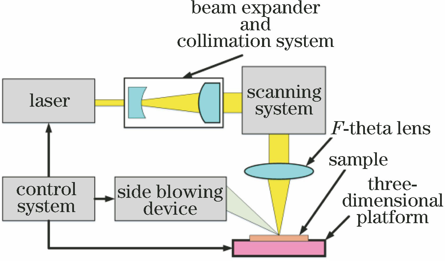
Fig. 1. Schematic of laser texturing equipment
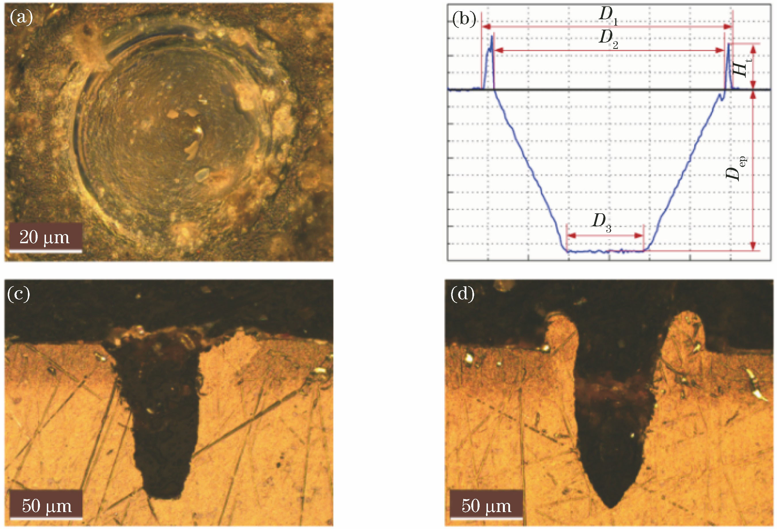
Fig. 2. Morphologies of the texturing pits. (a) Two-dimensional metallographic diagram; (b) cross-section schematic; (c) inverted trapezoid metallographic diagram; (d) inverted triangle metallographic diagram
Fig. 3. Characteristic parameters of pits versus pulse energy
Fig. 4. Morphologies of typical pits obtained at different pulse energies. (a) E =150 mJ; (b) E =200 mJ; (c) E =250 mJ
Fig. 5. Characteristic parameters of pits versus pulse width
Fig. 6. Morphologies of pits obtained at different pulse widths. (a) τ =200 μs; (b) τ =100 μs; (c) τ =50 μs
Fig. 7. Laser texturing pits' surface morphology obtained at different pulse widths. (a) τ =90 μs; (b) τ =80 μs; (c) τ =60 μs; (d) τ =50 μs
Fig. 8. Characteristic parameters of pits versus number of laser pulses
Fig. 9. Morphologies of pits obtained at different number of laser pulses. (a) n =1; (b) n =10; (c) n =20
Fig. 10. Characteristic parameters of pits versus defocusing amount
Fig. 11. Morphologies of typical pits obtained at different defocusing amount Δ
|
Table 1. Main performance parameters of Nd∶YAG pulsed laser pumped by LD
|
Table 2. Main components of 3A21 aluminum alloy
|
Table 3. Parameters of laser texturing process

Set citation alerts for the article
Please enter your email address
© Copyright 2018-2021 | Chinese Laser Press. All Rights Reserved 沪ICP备15018463号-20