Meng-Chang Hsieh, Jiun-You Lin, Chia-Ou Chang. Measurement of small wavelength shifts based on total internal reflection heterodyne interferometry[J]. Chinese Optics Letters, 2016, 14(8): 081202
Copy Citation Text
This Letter presents a method of an optical sensor for measuring wavelength shifts. The system consists of a diffraction grating and a total internal reflection heterodyne interferometer. As a heterodyne light beam strikes a grating, the first-order diffraction beam is generated. The light penetrates into a total internal reflection prism at an angle larger than the critical angle. A wavelength variation will affect the diffractive angle of the first-order beam, thus inducing a phase difference variation of the light beam emerging from the total internal reflections inside the trapezoid prism. Both the experimental and theoretical results reveal that, for the first-order diffractive beam, the sensitivity and resolution levels are superior to 5°/nm and 0.006 nm, respectively, in the range of wavelength from 632 to 634 nm, and are superior to 3.1°/nm and 0.0095 nm in the range from 632 to 637 nm. For the theoretical simulation of the fourth-order diffractive beam, they are superior to and 0.0047 nm in the range from 632 to 637 nm.
The accurate measurement of a wavelength shift plays a crucial role in many research fields, such as pressure sensing[1], temperature sensing[2], optical fiber communication[3], and monochromatic interferometer applications. Especially in monochromatic interferometers, the basic Michelson interferometer consists of a monochromatic light source, a beam splitter (BS), and two mirrors. It relies on the principle of constructive and destructive interference as one mirror is fixed and the other is moved. It is indispensable to measure the wavelength variations[4] of a light source to ensure the measurement resolution. Therefore, the technique of optical sensors for measuring a small wavelength shift is becoming important[5]. In addition, the measurement methods of wavelength shifts are extensive. Several methods, including passive detection, diffraction type, and interferometric phase detection schemes, have been proposed to monitor the wavelength differences[6–16]. The passive detection system divides the scattered light from a Bragg grating into two parts, one of which is filtered in proportion to its wavelength, while the other is employed as a reference to compensate for intensity variations. The diffraction-type schemes evaluate the wavelength difference by an intensity variation of the first-order diffraction light beam from a diffraction grating. However, the measurement accuracy of these methods may be decreased because of the surrounding light and the scattered light interfering with the associated light[16]. Conversely, our interferometric phase detection scheme can detect the wavelength based on the measurement of phase variation and does not have these two aforementioned shortcoming[16].
This study demonstrates a total internal reflection (TIR) heterodyne interferometric sensor for measuring wavelength shifts and derives theoretical equations. The experimental setup is composed of a heterodyne tunable laser light source (Model 6300-TN, New Focus, the laser tunes the different wavelengths by rotating the angle of reflective grating, which can reflect and control the output wavelength of the laser diode light), a grating, and a trapezoid prism. When a heterodyne tunable laser light beam is normally incident on the grating, the first-order diffraction beam is produced. Then, the tunable laser light is guided into a multi-TIR trapezoid prism at an angle larger than the critical angle. A wavelength variation of the tunable laser will affect the diffractive angle of the first-order beam, thus inducing a phase difference variation of the light beam that emerges from the TIRs inside the trapezoid prism. The experimental and theoretical results reveal that, for the first-order diffractive beam, the sensitivity and resolution levels are superior to 5°/nm and 0.006 nm, respectively, in the range of wavelength from 632 to 634 nm, and are superior to 3.1°/nm and 0.0095 nm in the range from 632 to 637 nm. This study also demonstrates a theoretical simulation of phase difference versus wavelength (632 to 637 nm) of the second- and fourth-order diffractive beams that show that the higher order the diffractive beam is, the larger the phase difference becomes.
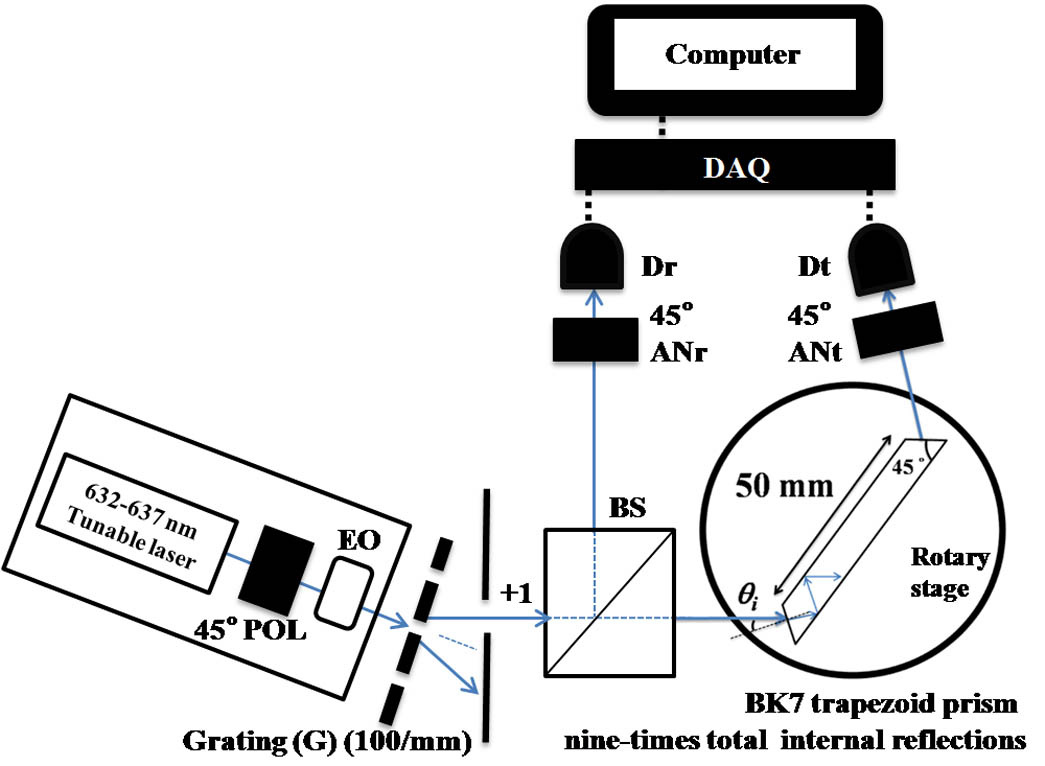
Figure 1 illustrates the experimental setup for this measurement. For convenience, the -axis is set in the direction of light propagation, and the -axis is set perpendicular into the plane of the Letter. After the laser light passes through a 45° polarizer (POL) and an electro-optic modulator (EO) (Model 4002, New Focus) driven at an angular frequency , the Jones vector of amplitude has the form[17]:
Sign up for Chinese Optics Letters TOC. Get the latest issue of Chinese Optics Letters delivered right to you!Sign up now
Figure 1.Schematic diagram of the wavelength shifts measurement architecture.
The heterodyne light beam is normally incident on a grating () with a period . The wavelength of incident light is adjusted from 632 nm () to 637 nm for 1 nm every step. After the heterodyne light entered into the , the first-order diffraction beam is generated. According to the grating equation[18], its diffractive angle is given asThe diffractive beam is divided into a reflected beam and a transmitted beam by a BS. The reflected beam proceeds through an analyzer () whose transmission axis is at 45° to the -axis, and produces the amplitude , which is entering to the end at a photodetector . The amplitude can be expressed as follows[17]: and the intensity detected by is where and represent the phase difference between - and -polarizations produced by the passage through the BS and of the laser beam. The intensity is used as the reference signal.
The transmitted beam is guided to propagate through a trapezoid prism. The light beam is subsequently incident at (, change with respect to , Fig. 1) on the one end face of the prism (with the refractive index of ). is at an angle larger than the critical angle.
The light in the trapezoid prism undergoes nine TIRs. The light output from the prism travels through an analyzer () whose transmission axis is 45° to the -axis for interference, which is entering the end at a photodetector . The amplitude can be expressed as follows: and the intensity detected by is which serves as a test signal. When the wavelength changes by , will be changed. It will cause the test signal to produce a phase change in ( is the phase difference between the - and -polarizations produced by TIRs inside the prism). , which is derived using Fresnel’s equation, can be expressed as follows: The intensities and are sent to a lock-in amplifier (LIA) for analysis, enabling the phase difference to be accurately measured.
To compare the intensities and , there is a phase difference: minus is the background signal. The background signal can be measured before the measurement of the wavelength versus phase difference from the TIRs inside the trapezoid prism. In order to find , it is only necessary to remove the trapezoid prism and then measured the transmitted beam and reflective beam from the BS. The transmitted beam directly enters through the and . Therefore, the wavelength versus the phase difference (the background signal) of the BS can be measured and deduced.
Figure 2 demonstrates the experimental results and theoretical simulation to show the consistent trend and validity of this method. The 45° transmission axis of the incident laser light source was chosen. The laser light source was modulated by an EO and used as a heterodyne light source (Fig. 1). The frequency difference between the - and -polarized components was 1 kHz, and the sampling rate of LIA (DAQ-PCI-6024E: the lock-in amplifier was designed by Labview-2011, National Instruments) was 10 kHz. The resolution of the LIA was 0.01°. The refractive index (BK7), and the critical angle is 5.6031°. The initial incident angle controlled by the rotary stage (SGSP-60YAW: the resolution of the rotary stage is 0.0025°, Opto Sigma) and the grating period was chosen. Figure 2 displays the first-order () diffraction beam relation curve of phase difference versus the wavelength (). The simulation and experimental results demonstrate the feasibility of this method.
Figure 2.Relation curve of phase difference and wavelength.
The relation curve between this system sensitivity and wavelength is produced by the differential of theoretical value on Fig. 2. The sensitivity of approximately higher than 5 and can be achieved in the ranges of 632 to 634 nm and 632 to 637 nm, as seen in Fig. 3.
Figure 3.Theoretical simulation of sensitivity versus wavelength.
As the wavelength increases by , the condition causes the diffractive angle of the first-order beam to slightly change by . According to Eq. (2), the incident angle on the trapezoid prism is therefore changed by , resulting in a noticeable phase-difference variation . The relationship between and can be expressed as follows: As revealed in Eq. (8), the can be estimated through the measurement of . In addition, the resolution of this system[17] can be defined as where is the phase difference error. The second harmonic error (SHE)[19,20], the polarization mixing error (PME)[17,19,20], the angular resolution of lock-in amplifier (ARLIA), the imperfection on light-path alignment, and the grating period error (GPE) all affected . The SHE was caused by small angular deviations of the transmission axes of POL or analyzers. The deviation quantity was determined by a resolution of an optical polarimeter (the resolution of polarimeter in this experiment was 0.5°). The PME was caused by the imperfection of polarization and was predictable[20] based on the extinction ratio effect of a polarizer. The GPE was caused by the imperfection of grating period and produced phase errors that could be seen from the parameter , which appeared in Eq. (2) and (7).
The experiments had calibrated the light paths to reduce the error factor. If a precise period grating was used, the GPE could be eliminated. The total phase difference error after the deduction of the predictable PME was estimated to approach (the summation of SHE and ARLIA), as seen in Table 1.
Uncertainty errors
Phase errors (deg.)
Note
The SHE
0.02
The resolution of the polarimeter (for calibrating the POL, ANr, and ANt) in this experiment was 0.5°
The PME
0.35
The PME (the extinction ratio of the polarizer was 10−5) was predictable and could be deduced[20].
The ARLIA
0.01
The GPE
0.22
The theoretical calculation based on 3% period errors (632 to 633 nm, Δλ=1nm)
The ranges are from 632 to 634 nm and 632 to 637 nm, as shown in Fig. 3, and Fig. 4 shows that the resolution levels are found to be below and 0.0095 nm. They are evaluated by the reciprocal of sensitivity (Fig. 3) and Eq. (9) at .
Figure 4.Theoretical simulation of resolution versus wavelength.
The sensitivity can be improved by increasing the number of TIRs, but this requires a longer trapezoid prism of the same width. The smaller period grating can also achieve the higher sensitivity that can be seen from Eq. (2). If the order of diffraction beam is , Eq. (2) becomes Equation (10) revels that the larger the is, the higher the sensitivity is, but the lower the light intensity is[18]. Figure 5 shows that the phase difference of the order is two times larger than that of order (the experimental results used the diffraction light of order ) in the range between 632 and 637 nm. For the second-order diffractive beam, the theoretical sensitivity and resolution levels are superior to and 0.0067 nm, respectively, in the range of wavelength from 632 to 637 nm. For the fourth-order diffractive beam, they are superior to and 0.0047 nm in the range from 632 to 637 nm.
Figure 5.Relation curve of phase difference and wavelength of the diffraction beam with different orders.
In conclusion, a novel and simple method for measuring a small wavelength shift is proposed. Both the experimental and theoretical results reveal that, for the first-order diffractive beam, the sensitivity and resolution levels are superior to and 0.006 nm, respectively, in the range of wavelength from 632 to 634 nm, and are superior to 3.1°/nm and 0.0095 nm in the range from 632 to 637 nm. For the theoretical simulation of the fourth-order diffractive beam, they are superior to and 0.0047 nm in the range from 632 to 637 nm. The proposed approach yields stable benefit and high resolution based on the advantage of common path[17] and multi-TIR heterodyne interferometry.
Meng-Chang Hsieh, Jiun-You Lin, Chia-Ou Chang. Measurement of small wavelength shifts based on total internal reflection heterodyne interferometry[J]. Chinese Optics Letters, 2016, 14(8): 081202