Abstract
We investigate numerically the pattern formation in 2-μm thulium-doped Mamyshev fiber oscillators, associated with the dissipative Faraday instability. The dispersion-managed fiber ring oscillator is designed with commercial fibers, allowing the dynamics for a wide range of average dispersion regimes to be studied, from normal to near-zero cavity dispersion where the Benjamin–Feir instability remains inhibited. For the first time in the 2-μm spectral window, the formation of highly coherent periodic patterns is demonstrated numerically with rates up to . In addition, irregular patterns are also investigated, revealing the generation of rogue waves via nonlinear collision processes. Our investigations have potential applications for the generation of multigigahertz frequency combs. They also shed new light on the dissipative Faraday instability mechanisms in the area of nonlinear optical cavity dynamics.1. INTRODUCTION
Owing to the advantages of compactness, alignment-free, and high pulse quality, passively mode-locked fiber lasers have been extensively investigated in the past two decades. Ultrafast fiber lasers benefit numerous areas such as fiber communication engineering, micromachining, and biomedical imaging, as well as provide an excellent platform for investigating ultrafast nonlinear dynamics. Various techniques are generally implemented to achieve passive mode locking in fiber lasers, utilizing the nonlinear optical response of saturable absorbers. This relies on engineered materials such as semiconductor saturable absorber mirrors (SESAMs) [1], single-wall carbon nanotubes (SWNTs) [2], graphene [3], transition-metal dichalcogenides (TMDs) [4,5], or those based on nonlinear interference, for instance with the nonlinear polarization evolution (NPE) mode locking [6] or with the use of a nonlinear amplifying loop mirror (NALM) [7].
Recently, Mamyshev oscillators (MOs) have attracted increasing research interests as a promising alternative to the passive mode locking of fiber lasers. The concept of these oscillators originates from the scheme of cascaded reshaping and reamplification (2R) regenerators first proposed by Mamyshev in optical fiber transmission systems [8]. The pulse-shaping approach is based on self-phase-modulation (SPM)-induced spectral broadening, followed by offset filtering, providing a nonlinear power transfer function similar to that of a saturable absorber [9]. Mamyshev oscillators are constructed from a pair of spectrally offset 2R regenerators in a closed loop [10,11], which regenerate circulating pulses twice per cavity roundtrip. Up to now, investigations of Mamyshev oscillators have revealed their wide potential for engineering applications, such as signal buffering [11], random number generation [9,12], and high-energy short-pulse generation [13–19]. From the theoretical standpoint, stable pulsed regimes in Mamyshev oscillators are possible in the presence of a stable dynamical attractor. The latter results from a composite balance among the effects of nonlinearity, dispersion, gain, and loss, similar to the case of a mode-locked laser [20]. However, in contrast with mode-locked lasers, the variety of complex dynamics of Mamyshev oscillators has not been extensively investigated. The present article aims at filling this gap, even partially, with the help of numerical simulations.
Fundamentally, an oscillator based on true optical regenerators will hardly be a self-starting one. Indeed, the function of an optical regenerator is to regenerate “0”s as well as “1”s, so that starting from a low intensity level will not lead to circulating pulses. By essence, regeneration should not create patterns but just maintain the integrity of a message. Consequently, pulsed sources based on Mamyshev oscillators usually require pulse injection, to get above the “0” and enter the “1” attracting state. Nevertheless, by exploring the range of the cavity parameters, it has been shown that modulation instability (MI) processes could take place within oscillators sufficiently close to the definition of a Mamyshev oscillator. MI is a ubiquitous mechanism in nonlinear optical systems, leading to the exponential growth of a periodic modulation of a homogeneous spatiotemporal background solution. Several classes of MI have been investigated in fiber resonators such as the Benjamin–Feir instability (BFI) [21–23], the Turing instability (TI) [24–26], and the Faraday instability (FI) [25–28]. Very recently, the dissipative Faraday instability (DFI), as a novel type of MI, has been proposed for high-repetition-rate harmonic mode locking [29–33]. In the regime of the DFI, the symmetry breaking of the homogeneous solution is induced by the periodic spectral losses arranged in a zigzag way, leading to the spectral sideband generation and ultimately the pattern formation [29–31]. The application of the DFI shows an interesting potential for the generation of multigigahertz frequency comb generation [29–33].
Sign up for Photonics Research TOC. Get the latest issue of Photonics Research delivered right to you!Sign up now
Interestingly, the Mamyshev oscillators, with periodic offset spectral filtering in an alternating fashion, provide a promising platform for the investigation of the DFI physical mechanisms in fiber optics. Echoing the first experimental demonstration in a linear Raman fiber oscillator operating at the waveband of 1.5 μm [29], the high-repetition-rate harmonic mode locking, induced by the DFI mechanism, has also been theoretically investigated in a 1.0-μm waveband all-normal-dispersion (ANDi) fiber oscillator [32]. However, note that, there has not been to date any experimental or theoretical investigation of the DFI pattern formation in Mamyshev oscillators operating at the 2-μm waveband. Considering the potential applications of 2-μm laser sources in the midinfrared (MIR) molecular spectroscopy, medicine, and telecommunication networks, it is beneficial to expand the investigation of this novel DFI mechanism to all the three major fiber laser operation wavelengths from 1.0 to 2.0 μm.
In the present paper, we report on the first numerical investigations of the DFI pattern formation in 2-μm thulium-doped Mamyshev fiber oscillators, conducted with realistic parameters involving commercially available single-mode optical fibers. Note that, in the earlier investigations of the DFI pattern formation [29,32], fibers with large normal group velocity dispersion (GVD) are implemented to inhibit the initiation of the BFI. Given that standard silica-based optical fibers generally feature a large anomalous chromatic dispersion at the wavelength around 2 μm, a specialty dispersion-compensation fiber with a relatively high normal GVD is utilized in our investigations. Under the dispersion-managed regimes, with large net normal or near-zero cavity dispersion, up to ultrahigh-repetition-rate harmonic mode locking is demonstrated. Moreover, the coherence properties of the regular and irregular patterns associated with the DFI are also investigated and reveal the generation of optical rogue waves (RWs) in the irregular patterns via nonlinear pulse collision. Our investigations might benefit the further understanding of this novel DFI mechanism in laser physics and nonlinear science.
2. THEORETICAL MODEL
The scheme diagram of the 2-μm Tm fiber-based Mamyshev oscillator is shown in Fig. 1. The unidirectional ring cavity is made up of two Tm-doped gain fiber sections alternated with two passive fiber sections. The pulse propagation in the Mamyshev oscillators is modeled with a parameter-managed model, which includes lumped spectral filters as well as the generalized nonlinear Schrödinger (NLS) equation [32,34] for propagation in commercially available optical fibers: where is the electric field slowly varying envelope, is the propagating coordinate, and is the time in a frame of reference moving with the group velocity. is the GVD, and is the nonlinear Kerr coefficient. The gain coefficient of the Tm-doped fibers, whose bandwidth is , is defined as where is the small-signal gain, and is the saturation energy. In our simulations, the highly doped SM-TSF-5/125 and UHNA4 fibers from Nufern are chosen as the Tm-doped gain fibers and the normal dispersion passive fibers, respectively [34,35].
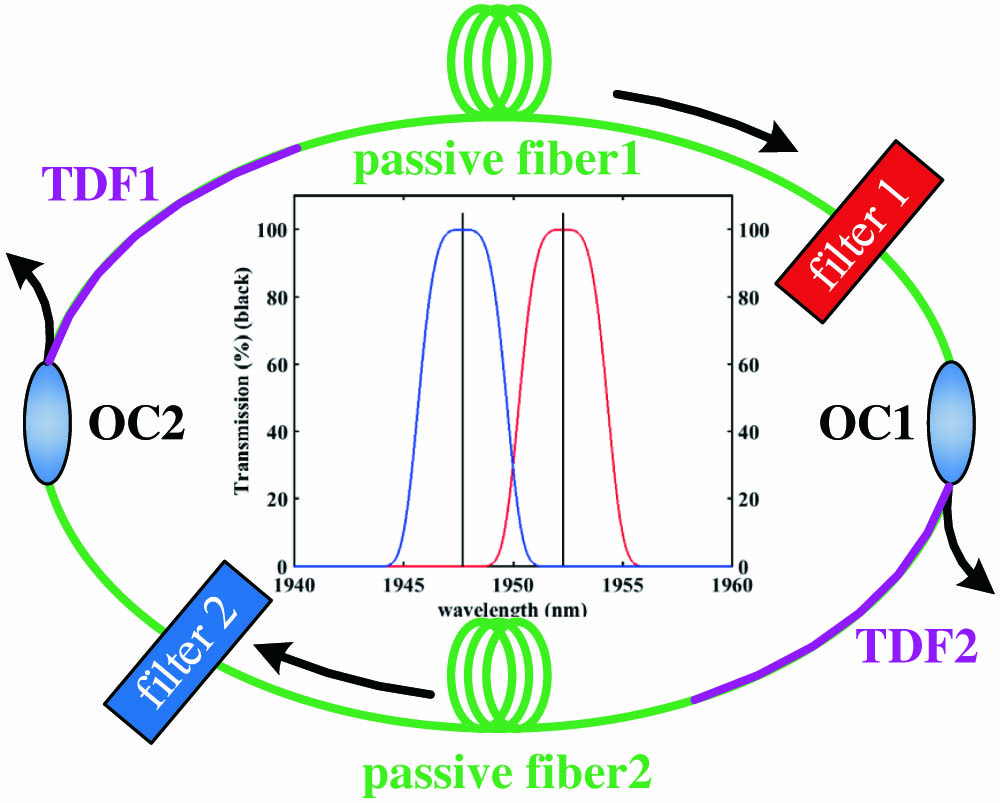
Figure 1.Schematic diagram of the 2-μm fiber ring cavity in a Mamyshev oscillator configuration. OC, optical coupler; TDF, Tm-doped gain fiber; filter 1, longer-wavelength super-Gaussian spectral filter; filter 2, shorter-wavelength super-Gaussian spectral filter; passive fiber, the commercial normal dispersion fiber (NDF).
The functions of the offset spectral filters are described by multiplication of the electric field by the super-Gaussian transmission profiles in the frequency domain. The frequency detuning between the spectral filters is described as , while the 3-dB spectral filter bandwidth is represented as . The output coupling ratios of the optical couplers are described as and .
The following parameters are used for the following simulations: , , , , , , , , and . The bandwidth value of the TDF matches well with the parameters of the commercial Tm-doped fibers as well as our previous experience on numerical investigations. For this central parameter case, the total GVD amounts to . The small-signal gain and the saturation energy are adjusted as the control parameters to describe the energy pumped into the cavity.
3. RESULTS AND DISCUSSION
Numerical simulations are performed utilizing the standard split-step Fourier method. Firstly, we injected a small Gaussian-shaped pulse as the initial condition, to speed up the convergence of the algorithm towards the stationary operation state, which is an attracting state. By appropriately adjusting the oscillator parameters of the cavity gain and the frequency detuning between the filters, stable single pulse operation can be achieved, as depicted in Fig. 2. The temporal evolution during per cavity roundtrip is described in Fig. 2(a). The Gaussian-shaped pulse, after being strongly filtered by the shorter-wavelength filter, experiences a remarkable intensity increase during the propagation in the short section of the highly doped TDFs, reaching tens of kilowatts before entering the normal dispersion passive fiber. Owing to the high dispersion value of the passive fiber, the pulse broadens rapidly in the temporal domain and its intensity decreases without suffering wave breaking. However, the pulse shape deviates from the Gaussian shape with part of the pulse energy transformed into increasing temporal oscillating wings, before the interaction with the longer-wavelength filter takes place. The pulse is reshaped after propagation through the longer-wavelength spectral filter, continuing another temporal and spectral evolution until going through the shorter-wavelength filter again. The pulse evolution dynamics indicates that the spectral filters play a key role in the pulse shaping. In this paper, the temporal and spectral evolutions over hundreds of cavity roundtrips are taken at the output of OC1. We also investigate the temporal and spectral evolutions by roundtrips at different positions in the oscillators, exhibiting similar tendency to those at the output of OC1.

Figure 2.Spatiotemporal dynamics of single pulse operation: (a) temporal spectral evolution during per cavity roundtrip. A, B, C, D, E, and F represent the TDF1, passive fiber1, filter1 + OC1, TDF2, passive fiber2, and filter2 + OC2; (b) temporal (blue) and frequency chirping (red) profiles after the interaction with the longer-wavelength filter; (c) spectral pulse profile (blue) after the longer-wavelength filter (red); (d) spectral evolution over 300 roundtrips at the output of OC1 (color scale for the optical intensity, in dB). The cavity parameters are , , .
In our simulations, the number of pulses per roundtrip can be increased by using a higher pump power, similar to the earlier reports in the erbium-doped and ytterbium-doped Mamyshev oscillators [9,14]. Interestingly, Fig. 3 shows the temporal evolution of the soliton pair operation, for the same frequency detuning between the filters, but at higher cavity gain. As illustrated in Fig. 3(a), the two pulses of the soliton pair experience the same temporal evolution, similar to the situation of the single pulse operation. Figure 3(b) depicts the pulse shape after the longer-wavelength spectral filter, indicating that the bound solitons have the same intensity and pulse duration of 2.1 ps, fitted by the Gaussian profile, and the pulse separation is 14.5 ps. The spectrum in Fig. 3(c) exhibits a regular high-contrast modulation period of 0.89 nm, which coincides with the pulse separation. The phase relationship is also calculated, with a phase difference of 3.31 rad, indicating the out-of-phase condition. Because of the significant pulse broadening, the overlap of the adjacent pulse wings is observed after propagation through the normal dispersion passive fibers. After the filtering effect of the spectral filters, the soliton pairs are reshaped, with the oscillating temporal wings inhibited. The long-term pulse evolution is also measured, revealing the feature of stationary soliton pair operation with constant pulse separation and phase relationship. Note that, with certain different initial conditions, the same soliton molecule operation can be achieved over hundreds of cavity roundtrips, which is related to the concept of fixed-point soliton molecule attractor in the dissipative systems [20]. We have not yet observed soliton molecules with more complex self-organizations such as soliton triplets or quartets, but we believe there is no fundamental reason why they should not be observed, following the analogy with the ultrafast fiber laser dynamics. Numerically, it only requires more precision and computing time to validate the existence of such structures, in addition to the selection of appropriate parameter settings.
Figure 3.Spatiotemporal dynamics of soliton pair molecule operation: (a) temporal evolution during per cavity roundtrip. A, B, C, D, E, and F represent the TDF1, passive fiber1, filter1 + OC1, TDF2, passive fiber2, and filter2 + OC2; (b) temporal and frequency chirping profiles after the longer-wavelength filter; (c) spectral profiles after the longer-wavelength filter; (d) spectral evolution over 300 roundtrips at the output of OC1. The remaining parameters are , , .
By further decreasing the frequency detuning between the spectral filters with fixed cavity gain, the number of pulses propagating in the oscillator increases, forming a random pulse train operation [11,32]. Although the pulses propagating in the cavity appear randomly in time, they maintain their relative position and keep a stable profile over the cavity roundtrips, as depicted in Fig. 4(a), showing the potential for random number generation [12]. The pulses experience a periodic intensity increase in the TDFs and temporal broadening in the passive fibers, twice per cavity roundtrip. Note that, with the increasing number of pulses involved in such a multipulse regime, the pulse intensity decreases and the temporal oscillating wings of the pulses are inhibited within a certain degree, showing the link between oscillating pulse wings and the accumulated nonlinearity in the passive fibers. As shown in Figs. 4(c) and 4(d), the spectral evolution reflects a reduced coherence owing to a random pulse train with nonstationary and arbitrary phase relationships between the adjacent pulses.
Figure 4.Spatiotemporal dynamics of random pulse train operation: (a) temporal and (c) spectral evolution over 300 roundtrips at the output of OC1; (b) temporal and (d) spectral evolution during per cavity roundtrip. A, B, C, D, E, and F represent the TDF1, passive fiber1, filter1 + OC1, TDF2, passive fiber2, and filter2 + OC2. The remaining parameters are , , .
The steady-state regimes are significantly affected by the frequency detuning between the filters. Regular patterns form via the DFI mechanism when the frequency detuning is decreased to a certain threshold [31,32]. An example of regular pattern formation is illustrated in Figs. 5 and 6. The temporal and spectral evolution over cavity roundtrips is measured, revealing the ultrahigh harmonic mode locking operation. The temporal period of the pulse train is 11.1 ps, which corresponds to a repetition rate of 90 GHz, equivalent to the cavity harmonic, considering the fundamental frequency of 36.7 MHz. The single pulse profiles before and after the spectral filter are also analyzed, as depicted in Figs. 6(a) and 6(b). After the propagation in the passive fibers, the pulse profile ultimately reaches a parabolic shape, attributed to the self-similar evolution in the normally dispersive fiber [36]. After the interaction with the spectral filters, the pulse profile is reshaped into a Gaussian shape. It is worth noting that, although the DFI pattern formation has been shown for the 1.5-μm Raman fiber oscillator [29] and the 1.0-μm ANDi fiber oscillator [32], the coherence was limited by a large timing jitter in the systems. As pointed out in Ref. [32], such a timing jitter was induced by a combination of noise and wave breaking in the ultralong normal dispersion passive fibers with a length of several kilometers. In our simulations, as shown in Figs. 5 and 6, a stationary spectrum with high-contrast modulation is obtained, with a period of 90 GHz between the adjacent spectral comb lines. We conclude that the high spectral coherence in our investigations is attributed to the cavity structure improvement by using a relatively short cavity length of only several meters, showing the potential for highly coherent ultra-high harmonic mode locking in the future experimental research. This is facilitated at the wavelength of 2 μm, owing to the larger gain bandwidth of TDF and high normal dispersion of the commercial normal-dispersion fibers.
Figure 5.Spatiotemporal dynamics of regular pattern formation: (a) temporal and (c) spectral evolution over 300 roundtrips at the output of OC1; (b) temporal and (d) spectral evolution during per cavity roundtrip. A, B, C, D, E, and F represent the TDF1, passive fiber1, filter1 + OC1, TDF2, passive fiber2, and filter2 + OC2. The remaining parameters are , , .
Figure 6.Spatiotemporal profiles of regular pattern formation: single pulse temporal profiles (a) before and (b) after the interaction with the longer-wavelength filter; (c) pulse train temporal and phase profiles after the longer-wavelength filter; (d) spectral profile after the longer-wavelength filter.
The temporal and spectral evolution during one cavity roundtrip is displayed in Figs. 5(b) and 5(d). Notably, during the propagation in the normal dispersion passive fibers, due to the nonlinear Kerr effect, the envelope of the spectrum broadens. Consequently, the number of the spectral comb lines, involved in the harmonic mode locking pulse train, dramatically increases during the propagation, where the pulse energy is gradually spread over the spectral comb lines in the spectral wings. The spectral coherence is maintained through every cavity roundtrip, attributed to the inherent nature of the coherent phase coupling between each spectral comb line and the adjacent lines separated by the DFI frequency [29]. The phase relationship of the pulse train is also investigated, revealing that the phase difference is constant between the adjacent pulses, further confirming the temporal coherence of the harmonic mode locking. In our case, the repetition rate is mainly limited by the high pulse intensity of hundreds of watts, which is two orders of magnitude larger than that of Ref. [32]. By extension, it is therefore conceivable that further cavity parameter scaling will allow the generation of repetition rates well beyond 100 GHz. The large gain bandwidth of TDF is also a good asset for this prospect.
According to Refs. [29,32], the repetition rate of the regular patterns is in inverse relationship with the pulse intensity, influenced by complex parameter settings of the pump power and filter frequency detuning. Thus, the preciseness is limited in drawing the curves of the repetition rate versus a single variable of pump power or frequency detuning.
Our scheme of highly coherent ultrahigh-repetition-rate harmonic generation in Mamyshev oscillators provides a feasible alternative to the general methods of multigigahertz frequency comb generation in microresonators or inserting a Mach–Zehnder interferometer in the fiber cavity.
The stability of the DFI-induced pattern formation is significantly influenced by the frequency detuning between the filters. Irregular pattern generation can be observed by decreasing the frequency detuning under a certain threshold, with the repeated processes of pulse formation and annihilation during successive cavity roundtrips. Figures 7 and 8 depict two cases of the temporal and spectral evolution dynamics of the irregular patterns with different frequency detuning values. As discussed in Ref. [31], a weaker frequency detuning is insufficient to suppress the noisy background, which grows between pulses, leading to the emergence of nonlinear collision processes. Note that, the nonlinear collision processes become much more intense with smaller frequency detuning, where larger numbers of noisy waves are involved, significantly degrading the spectral coherence of the patterns, as shown in Figs. 7 and 8. The intensity fluctuation and temporal overlap are also observed among the adjacent pulses propagating per cavity roundtrip, as illustrated in Figs. 7(b) and 8(b). The interesting presence of Faraday pattern “islands” on a “sea” of spatiotemporally chaotic turbulence, as described in Ref. [33], is also observed. To counter the stabilizing effect of the gain bandwidth, which was noted in Ref. [33], a smaller detuning between filters can be used to enter the turbulent regime.
Figure 7.Spatiotemporal dynamics of irregular pattern formation: (a) temporal and (c) spectral evolution over 300 roundtrips at the output of OC1; (b) temporal and (d) spectral evolution during per cavity roundtrip. A, B, C, D, E, and F represent the TDF1, passive fiber1, filter1 + OC1, TDF2, passive fiber2, and filter2 + OC2. The remaining parameters are , , .
Figure 8.Spatiotemporal dynamics of irregular pattern formation: (a) temporal and (c) spectral evolution over 300 roundtrips at the output of OC1; (b) temporal and (d) spectral evolution during per cavity roundtrip. A, B, C, D, E, and F represent the TDF1, passive fiber1, filter1 + OC1, TDF2, passive fiber2, and filter2 + OC2. The remaining parameters are , , .
Interestingly, we found that the effect of nonlinear collision among the multipulse regimes could lead to the generation of optical RWs. In our investigations, an example of the temporal and phase profiles of the RWs’ generation is depicted in Fig. 9. The phenomena of optical RWs have drawn widespread research interests in nonlinear physics in recent years, leading to an outburst of publications realized in various optical systems, such as ultrafast fiber lasers [34,37,38], supercontinuum generation [39,40], parametric processes [41], and microresonators [42]. The significant wave height (SWH) is defined as the mean amplitude of the highest third of the waves, and the wave events higher than twice the SWH qualify as RWs [40]. In our investigations, the statistical properties of the pulse intensity distribution are investigated to give more insight into the nonlinear collision dynamics in the irregular patterns.
Figure 9.Temporal and phase profiles of the RWs’ generation after the longer-wavelength filter. The remaining parameters are , , .
Figure 10 illustrates the influence of the frequency detuning between the filters on RWs’ generation. The pulse intensity distributions of different regimes, before the OC1, are depicted. Figure 10(a) shows the statistics distribution of the harmonic mode locking, associated with the regular pattern formation. The pulse intensity distributes around the root mean square (RMS) of 126 W, revealing high stability of the pulse trains. We further calculate the statistical properties of the irregular pattern regimes. The small-intensity events below the threshold of 50 W are removed to avoid the divergence of the probability for small amplitude pulses, in relationship with the cutoff applied in any experiment [34,43].
Figure 10.Influence of the frequency detuning between the filters on RWs generation: histogram on log scale showing the statistics distribution of the pulse intensity for values of (a) 4.6 nm; (b) 5.4 nm; (c) 4.2 nm; (d) 2.8 nm; and (e) 2.0 nm; (f) PDF and number of events versus the frequency detuning between the filters. The remaining parameters are and .
We accumulate the events to form the intensity distribution histograms. As depicted in Fig. 10, with decreasing , the intensity fluctuation increases, leading to the long-tailed L-shaped distributions. As illustrated in Figs. 10(d) and 10(e), in the statistics distributions, the high-intensity events exhibit much higher probability of occurrence than expected from standard Gaussian or Rayleigh distributions. The probability density function (PDF) and number of events versus the value of are also calculated to give quantitative analysis of the RWs’ generation. The simulation results are shown in Fig. 10(f). The number of events per 500 roundtrips increases with the decrease of value, indicating the inefficient suppression of the noisy background for a weak frequency detuning between the filters. The PDF of RWs experiences a remarkable increase with the growth of the collision events, demonstrating that the generation of RWs is here associated with the occurrence probability of nonlinear pulse collisions. In our simulations, the statistics of the RWs at OC1 and OC2 are the same.
To further confirm that the DFI pattern formation remains a general property of the Tm Mamyshev oscillators operating at the 2-μm waveband, we conduct the numerical investigations in a second fiber ring setup. We use the same normal dispersion passive fibers, while the Tm-doped gain fibers are changed to the lightly doped CorActive TH512 fibers, with the dispersion value of and the nonlinear Kerr coefficient of [35]. Both Tm-doped fiber sections are chosen to be 1.5 m long. The length of both passive fiber sections is chosen to be 1.5 m, yielding a total cavity GVD close to zero, at . The fundamental repetition rate is 33 MHz. The spectral filter profiles and the output couplers remain the same. Single pulse, soliton molecules, and random pulse train operations can be successively obtained by appropriately adjusting the cavity parameters of the active fiber gain and filter frequency detuning.
With the proper cavity parameter settings, the regular pattern formation is achieved, illustrated in Figs. 11 and 12. The repetition rate is calculated to be 107.5 GHz, corresponding to the harmonic mode locking. The spectrum exhibits a high-contrast modulation, with the period of 107.5 GHz between the adjacent spectral comb lines. The temporal and spectral evolution during one cavity roundtrip is also measured, revealing similar dynamics to that of the highly doped Tm Mamyshev oscillator. The pulses of the harmonic mode locking have a Gaussian shape after the interaction with one spectral filter and gradually evolve into parabolic shape upon propagation in the oscillator until they interact with the next filter. The envelope of the spectrum broadens significantly through every cavity roundtrip, with the pulse energy transformed into the spectral comb lines in the spectral wings. The temporal coherence results from the fixed phase relationship among adjacent pulses. Interestingly, our numerical investigations show that, with such dispersion-managed cavity with near-zero total GVD, the BFI remains absent, while the DFI generates the pattern. This complements the prior results in Refs. [29,32], where large total GVD was implemented for DFI pattern formation.
Figure 11.Spatiotemporal dynamics of regular pattern formation in the near-zero dispersion fiber ring setup (see text): (a) temporal and (c) spectral evolution over 300 roundtrips at the output of OC1; (b) temporal and (d) spectral evolution during per cavity roundtrip. A, B, C, D, E, and F represent the TDF1, passive fiber1, filter1+OC1, TDF2, passive fiber2, and filter2+OC2. The remaining parameters are , , .
Figure 12.Spatiotemporal profiles of regular pattern formation: single pulse temporal profiles (a) before and (b) after the interaction with the longer-wavelength filter; (c) pulse train temporal and phase profiles after the longer-wavelength filter; (d) spectral profile after the longer-wavelength filter.
Similar to the case of the large-normal dispersion fiber ring oscillator, the irregular pattern can be obtained by further decreasing the frequency detuning of the filters under the same cavity gain parameters. Two cases of the temporal and spectral evolution dynamics of the irregular patterns are depicted in Fig. 13. With the lower value of frequency detuning, the nonlinear collision processes become much more frequent with larger numbers of noisy waves involved, confirming the role of frequency detuning in noise background suppression. Compared to the regular pattern, the spectral coherence is degraded with the emergence of the noisy waves. The intense nonlinear collision processes lead to extreme wave generation, which is further demonstrated by calculating the statistics distributions of the pulse intensity of the irregular pattern regimes. The intensity distribution histograms on log scale are illustrated in Fig. 14. Analogous to the results in the large-normal dispersion (highly doped) oscillator, with smaller frequency detuning, the histograms exhibit more significant deviation from the Gaussian or Rayleigh distributions, resulting in long-tailed L-shaped distributions. The proportion of RWs increases with the decrease of the filter frequency detuning . Meanwhile, the event number involved in the nonlinear collision processes increases with the decrease of value, as in the large-normal dispersion (highly doped) oscillator. For the first time, our simulations predict the occurrence of RWs in 2-μm Mamyshev oscillators and link these RWs with the nonlinear pulse collision processes.
Figure 13.Spatiotemporal dynamics of irregular pattern formation: (a) temporal and (b) spectral evolution over 300 roundtrips at the output of OC1 (the remaining parameters are , , ); (b) temporal and (d) spectral evolution over 300 roundtrips at the output of OC1 (the remaining parameters are , , ).
Figure 14.Influence of the frequency detuning between the filters on RWs’ generation: histogram on log scale showing the statistics distribution of the pulse intensity for values of (a) 3.7 nm; (b) 2.6 nm; and (c) 2.2 nm; (d) PDF and number of events versus the frequency detuning between the filters. The remaining parameters are and .
The DFI harmonic pattern formation is not achieved in the anomalous dispersion regime, due to the initiation of the BFI.
4. SUMMARY
In summary, we demonstrate numerically the DFI pattern formation in 2-μm Tm Mamyshev oscillators by employing the realistic parameters of commercially available optical fibers. The specialty high-normal GVD passive fibers are utilized to compensate the large anomalous chromatic dispersion of the gain fibers. Both highly doped and lightly doped Tm fibers are exploited to form the dispersion-managed regimes, with either large net-normal or near-zero cavity dispersion, inhibiting the initiation of the BFI. The prediction of up to highly coherent ultrahigh-repetition-rate harmonic mode locking expands the investigation of the recent DFI mechanism to all the three major fiber laser operation wavelengths from 1.0 to 2.0 μm. Meanwhile, chaotic pattern generation is also investigated, leading to the generation of RWs associated with the nonlinear collision processes. Our investigations could benefit the applied field of mid-IR multigigahertz frequency comb generation, as well as enhance the understanding of the DFI mechanisms in laser physics.
Acknowledgment
Acknowledgment. P. Wang acknowledges the visit to S. T. Cundiff Lab, Department of Physics, University of Michigan, Ann Arbor, MI, USA.
References
[1] U. Keller. Recent developments in compact ultrafast lasers. Nature, 424, 831-838(2003).
[2] A. Martinez, Z. Sun. Nanotube and graphene saturable absorbers for fibre lasers. Nat. Photonics, 7, 842-845(2013).
[3] B. Fu, Y. Hua, X. Xiao, H. Zhu, Z. Sun, C. Yang. Broadband graphene saturable absorber for pulsed fiber lasers at 1, 1.5, and 2 μm. IEEE J. Sel. Top. Quantum Electron., 20, 1100705(2014).
[4] W. Liu, L. Pang, H. Han, Z. Shen, M. Lei, H. Teng, Z. Wei. Dark solitons in WS2 erbium-doped fiber lasers. Photon. Res., 4, 111-114(2016).
[5] K. Zhang, M. Feng, Y. Ren, F. Liu, X. Chen, J. Yang, X. Yan, F. Song, J. Tian. Q-switched and mode-locked Er-doped fiber laser using PtSe2 as a saturable absorber. Photon. Res., 6, 893-899(2018).
[6] V. J. Matsas, T. P. Newson, D. J. Richardson, D. N. Payne. Selfstarting passively mode-locked fibre ring soliton laser exploiting nonlinear polarisation rotation. Electron. Lett., 28, 1391-1393(1992).
[7] A. F. J. Runge, C. Aguergaray, N. G. R. Broderick, M. Erkintalo. Raman rogue waves in a partially mode-locked fiber laser. Opt. Lett., 39, 319-322(2014).
[8] P. V. Mamyshev. All-optical data regeneration based on self-phase modulation effect. 24th European Conference on Optical Communication, 475-476(1998).
[9] K. Sun, M. Rochette, L. R. Chen. Output characterization of a self-pulsating and aperiodic optical fiber source based on cascaded regeneration. Opt. Express, 17, 10419-10432(2009).
[10] S. Pitois, C. Finot, L. Provost, D. J. Richardson. Generation of localized pulses from incoherent wave in optical fiber lines made of concatenated Mamyshev regenerators. J. Opt. Soc. Am. B, 25, 1537-1547(2008).
[11] M. Rochette, L. R. Chen, K. Sun, J. Hernández-Cordero. Multiwavelength and tunable self-pulsating fiber cavity based on regenerative SPM spectral broadening and filtering. IEEE Photon. Technol. Lett., 20, 1497-1499(2008).
[12] T. North, A. Al-kadry, M. Rochette. Analysis of self-pulsating sources based on cascaded regeneration and soliton self-frequency shifting. IEEE J. Sel. Top. Quantum Electron., 20, 612-618(2014).
[13] T. North, M. Rochette. Regenerative self-pulsating sources of large bandwidths. Opt. Lett., 39, 174-177(2014).
[14] K. Regelskis, J. Želudevičius, K. Viskontas, G. Račiukaitis. Ytterbium-doped fiber ultrashort pulse generator based on self-phase modulation and alternating spectral filtering. Opt. Lett., 40, 5255-5258(2015).
[15] Z. Liu, Z. M. Ziegler, L. G. Wright, F. W. Wise. Megawatt peak power from a Mamyshev oscillator. Optica, 4, 649-654(2017).
[16] W. Fu, L. G. Wright, F. W. Wise. High-power femtosecond pulses without a modelocked laser. Optica, 4, 831-834(2017).
[17] W. Fu, L. G. Wright, P. Sidorenko, S. Backus, F. W. Wise. Several new directions for ultrafast fiber lasers. Opt. Express, 26, 9432-9463(2018).
[18] P. Sidorenko, W. Fu, L. G. Wright, M. Olivier, F. W. Wise. Self-seeded, multi-megawatt, Mamyshev oscillator. Opt. Lett., 43, 2672-2675(2018).
[19] W. Liu, R. Liao, J. Zhao, J. Cui, Y. Song, C. Wang, M. Hu. Femtosecond Mamyshev oscillator with 10-MW-level peak power. Optica, 6, 194-197(2019).
[20] P. Grelu, N. Akhmediev. Dissipative solitons for mode-locked lasers. Nat. Photonics, 6, 84-92(2012).
[21] P. Franco, F. Fontana, I. Cristiani, M. Midrio, M. Romagnoli. Self-induced modulational-instability laser. Opt. Lett., 20, 2009-2011(1995).
[22] C. J. S. de Matos, D. A. Chestnut, J. R. Taylor. Low-threshold self-induced modulation instability ring laser in highly nonlinear fiber yielding a continuous-wave 262-GHz soliton train. Opt. Lett., 27, 915-917(2002).
[23] R. E. Kennedy, S. V. Popov, J. R. Taylor. Ytterbium gain band self-induced modulation instability laser. Opt. Lett., 31, 167-168(2006).
[24] S. Coen, M. Haelterman. Continuous-wave ultrahigh-repetition-rate pulse-train generation through modulation instability in a passive fiber cavity. Opt. Lett., 26, 39-41(2001).
[25] F. Copie, M. Conforti, A. Kudlinski, A. Mussot. Competing Turing and Faraday instabilities in longitudinally modulated passive resonators. Phys. Rev. Lett., 116, 143901(2016).
[26] F. Copie, M. Conforti, A. Kudlinski, S. Trillo, A. Mussot. Dynamics of Turing and Faraday instabilities in a longitudinally modulated fiber-ring cavity. Opt. Lett., 42, 435-438(2017).
[27] N. J. Smith, N. J. Doran. Modulation instabilities in fibers with periodic dispersion management. Opt. Lett., 21, 570-572(1996).
[28] K. Staliunas, C. Hang, V. V. Konotop. Parametric patterns in optical fiber ring nonlinear resonators. Phys. Rev. A, 88, 023846(2013).
[29] N. Tarasov, A. M. Perego, D. V. Churkin, K. Staliunas, S. K. Turitsyn. Mode-locking via dissipative Faraday instability. Nat. Commun., 7, 12441(2016).
[30] A. M. Perego, S. K. Turitsyn, K. Staliunas. Gain through losses in nonlinear optics. Light Sci. Appl., 7, 43(2018).
[31] A. M. Perego, N. Tarasov, D. V. Churkin, S. K. Turitsyn, K. Staliunas. Pattern generation by dissipative parametric instability. Phys. Rev. Lett., 116, 028701(2016).
[32] A. M. Perego. High-repetition-rate, multi-pulse all-normal-dispersion fiber laser. Opt. Lett., 42, 3574-3577(2017).
[33] A. M. Perego, S. V. Smirnov, K. Staliunas, D. V. Churkin, S. Wabnitz. Self-induced Faraday instability laser. Phys. Rev. Lett., 120, 213902(2018).
[34] P. Wang, D. Hu, K. Zhao, L. Jiao, X. Xiao, C. Yang. Dissipative rogue waves among noise-like pulses in a Tm fiber laser mode locked by a monolayer MoS2 saturable absorber. IEEE J. Sel. Top. Quantum Electron., 24, 1800207(2018).
[35] C. Bao, X. Xiao, C. Yang. Spectral compression of a dispersion-managed mode-locked Tm:fiber laser at 1.9 μm. IEEE Photon. Technol. Lett., 28, 497-500(2016).
[36] F. Ilday, J. Buckley, W. Clark, F. Wise. Self-similar evolution of parabolic pulses in a laser. Phys. Rev. Lett., 92, 213902(2004).
[37] J. Peng, N. Tarasov, S. Sugavanam, D. Churkin. Rogue waves generation via nonlinear soliton collision in multiple-soliton state of a mode-locked fiber laser. Opt. Express, 24, 24256-24263(2016).
[38] C. Lecaplain, Ph. Grelu, J. M. Soto-Crespo, N. Akhmediev. Dissipative rogue waves generated by chaotic pulse bunching in a mode-locked laser. Phys. Rev. Lett., 108, 233901(2012).
[39] M. Erkintalo, G. Genty, J. M. Dudley. Giant dispersive wave generation through soliton collision. Opt. Lett., 35, 658-660(2010).
[40] D. R. Solli, C. Ropers, P. Koonath, B. Jalali. Optical rogue waves. Nature, 450, 1054-1057(2007).
[41] K. Hammani, C. Finot, G. Millot. Emergence of extreme events in fiber-based parametric processes driven by a partially incoherent pump wave. Opt. Lett., 34, 1138-1140(2009).
[42] A. Coillet, J. Dudley, G. Genty, L. Larger, Y. K. Chembo. Optical rogue waves in whispering-gallery-mode resonators. Phys. Rev. A, 89, 013835(2014).
[43] J. M. Soto-Crespo, Ph. Grelu, N. Akhmediev. Dissipative rogue waves: extreme pulses generated by passively mode-locked lasers. Phys. Rev. E, 84, 016604(2011).

